2.00b Toy Product Design
Mini-breadboard Build
Build on mini-breadboard
Take out your mini-breadboard and place the Arduino Nano on it as shown below. If the USB connector is at the "top", there should be 2 rows to the right of the Nano and 3 rows to the left of the Nano.

Be sure to gently, but firmly, push the Nano completely into the breadboard. You should not be able to see any of the Nano's leads.
Install the breadboard
- Unpeel the protective cover off the adhesive backing on the back of the breadboard
- Place the breadboard in the housing with the USB end oriented toward the bottom.

Install the Control Button
- Find the control button.
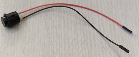
- Find the cutout on the side of the housing for the control button. Notice that the button has two flat sides and the cutout has two flat sides. Insert the control button wires through the cutout, then firmly, but gently, press the button into the housing.

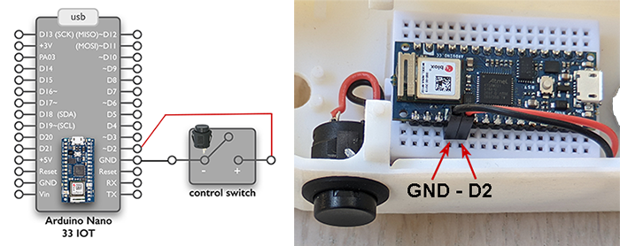
- Connect the wires of the control button to the Nano as shown below.
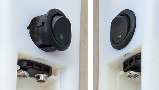
Install the Power Switch
- Find the power switch.
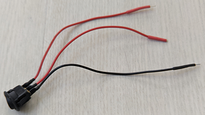
- Find the power switch cutout. Notice that the cutout has a notch in it and that the power switch has a tab that will go in the notch.
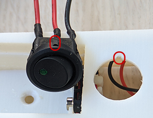
- Insert the power switch wires through the cutout, then firmly, but gently, press the button into the housing.
Install the Temperature Sensor
From the supply table, pick up 4 4-inch Male-to-Female jumper cables. You may choose from loose cables or a ribbon cable (peel off the next four colors), but the Vin cable must be from a ribbon cable (the loose cables are slightly shorter than the ribbon cable, and are not long enough for the Vin connection). You may pick cables of any color. Just keep track of which pin each color will be for. A pair of two ribbon cables connected together is recommended for the SCL/SDA lines.
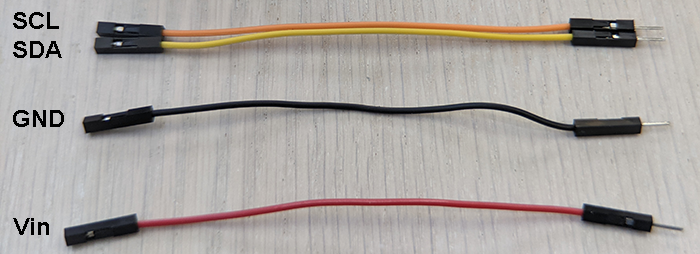
- Gently pry the temperature sensor off the breadboard (use the spudger, if necessary!).
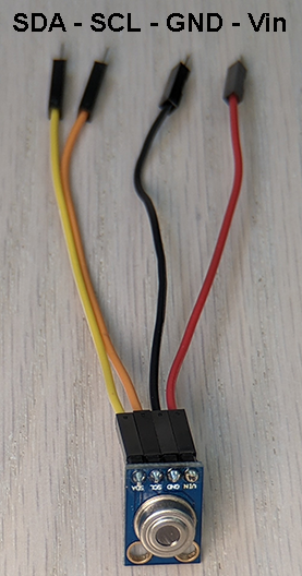
- Connect the jumper cables to the temperature sensor's header pins
- Notice that there are pegs in the housing for the holes in the temperature sensor's breakout board. Place the temperature sensor on the pegs, pushing firmly.
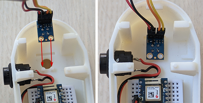
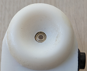
The sensor should be seated in the well on the exterior of the housing.
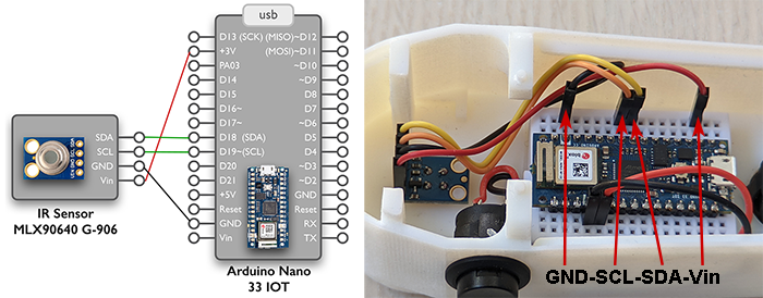
- Connect the jumper cables to the breadboard in the rows of the Nano as shown below.
- Find the temperature sensor restraint, which will help to hold the temperature sensor up against the back of the housing. Place it over the back of the temperature sensor as shown below.
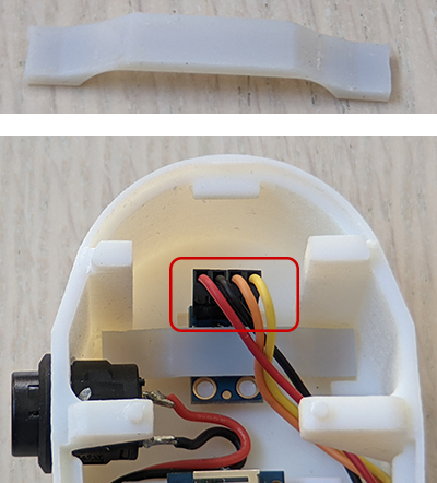
To make space for the display, bend the wires of the temperature sensor down into the case at the header (shown in red above).
Install the Display
From the supply table, pick up 3 loose 4" jumper cables (one for the SCK should be a longer cable separated from the ribbon cable) and a set of 6 ribbon cables still attached. You may pick cables of any color. Just keep track of which pin each color will be for.
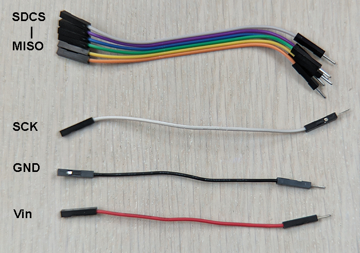
- Gently pry the temperature sensor off the breadboard (use the spudger, if necessary!).
- Connect the jumper cables to the display's header pins
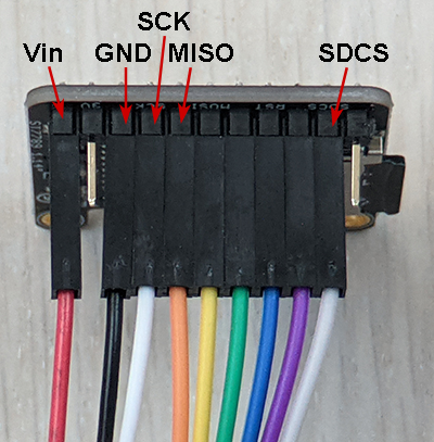
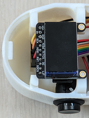
- Notice that there are pegs in the housing for the holes in the display's breakout board. Place the display on the pegs, pushing firmly. The friction between the pegs and the holes should hold most displays in place. If not, try to keep the display close to the correct final position at all times. While you may try to tape over the pegs, DO NOT place tape on the display itself, since peeling off the tape will destroy the display.
- Connect the jumper cables to the breadboard in the rows of the Nano as shown below.
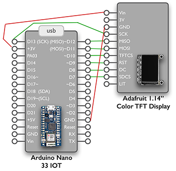
- First connect the Vin and SCK wires to the right side of the Nano.
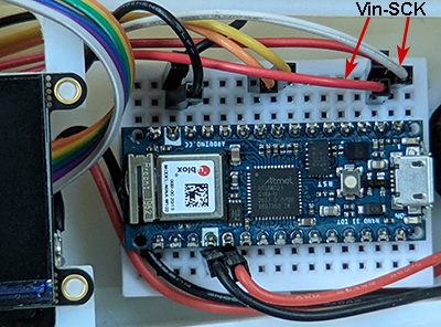
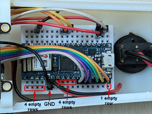
- On the left side of the Nano, connect the GND and the set of 6 ribbon cables.
Connect Power
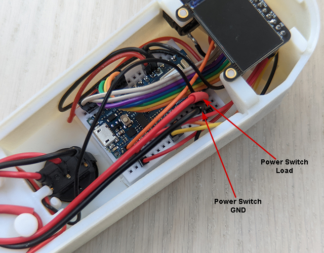
The circuit for providing battery power to the Nano is shown below:
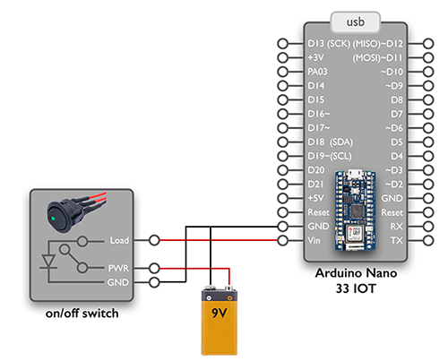
Follow the steps to build this circuit:
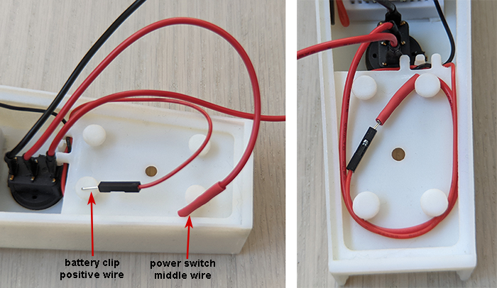
- Connect the positive wire from the 9V battery clip to the middle wire of the power switch. If the connection is loose, reinforce with electrical tape. Excess wires may be wound around the pegs on the back of the battery holder.
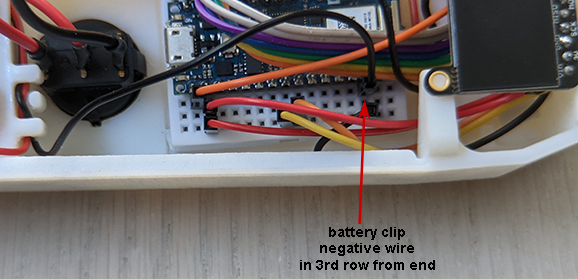
- Connect the negative wire from the battery clip to GND on the left side of the Nano.
Testing and Troubleshooting
Now that the entire circuit has been rebuilt, it's time to test all the wiring! Place a 9V battery in the battery clip.
Flip the power switch. The LED should light up. If it doesn't, there is something wrong with your power circuit wiring.
Take a look at your Nano, the light should be on on the microcontroller. If there isn't, then something is wrong with your power circuit wiring.
Take a look at your display, it should load up the logo and then your welcome message. If it doesn't, check for the following:
- Did you load the program with the line "while (!Serial);" commented out onto your microcontroller?
- Is there a SD card in the display module?
- There is a problem with the display wiring. Check that everything is pushed into the breadboard and that the display wiring connections are all there and in the right places.
Display working? Now try the control button. If there is no reaction to the button press (meaning nothing displayed at all on the display), check the control button wiring.
If the message is "Take Temp" that means that a long button press was detected but no temperature reading has been stored yet. You need to press the button more quickly to trigger a short button press in order to take a temperature reading or adjust the code to allow for a longer time for short button presses. Default is 1/2 second or more is a long button press.
If you can't figure out the issue, run the program from the computer with the "while (!Serial);" line not commented out so that you can see all messages in the Serial Monitor. You can pry up the edge of the breadboard with something stiff, like a screwdriver or scissor blade, just enough to put in the USB cable.


