 |
 |
| CAR DIFFERENTIAL | ||
| QUESTIONS OR COMMENTS | ||
 |
AUTHOR: | Ali Pearlman |
| E-MAIL: | alip@MIT.EDU | |
| COURSE: | 2 | |
| CLASS/YEAR: | 3 | |
MAIN FUNCTIONAL REQUIREMENT(s): Distribute power from car transmission shaft to a pair of Left-Right wheels (1ST FUNCTIONAL REQUIREMENT) while allowing wheels to rotate at different speeds (SECOND FUNCTIONAL REQUIREMENT).
DESIGN PARAMETER: Differential
HISTORY: The differential was first invented in China, in the third century, A.D.
GEOMETRY/STRUCTURE:
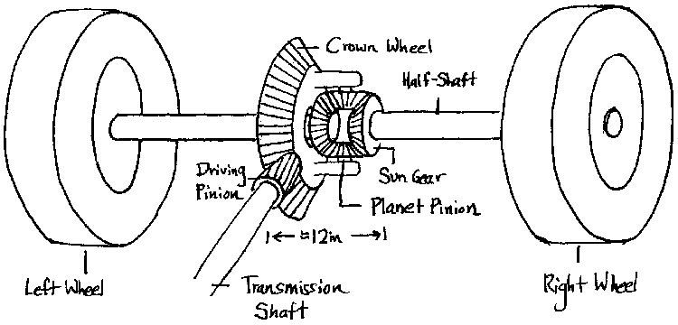 |
| Components In A Differential System |
Gear Teeth: The crown wheel and drive pinion teeth are helical, allowing for up-and-down movement in rough or uneven road conditions.
EXPLANATION OF HOW IT WORKS/ IS USED:
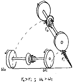
Why use a Differential?: When a car turns a corner, one wheel is on the "inside" of a turning arc, and the other wheel is on the "outside." Consequently, the outside wheel has to turn faster than the inside one in order to cover the greater distance in the same amount of time. Thus, because the two wheels are not driven with the same speed, a differential is necessary. A car differential is placed halfway between the driving wheels, on either the front, rear, or both axes (depending on whether it’s a front-, rear-, or 4-wheel-drive car). In rear-wheel drive cars, the differential converts rotational motion of the transmission shaft which lies parallel to the car’s motion to rotational motion of the half-shafts (on the ends of which are the wheels), which lie perpendicular to the car’s motion.
 |
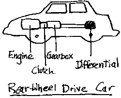 |
| In Turns, Wheels Are at Different Speeds | Location of Differential In Car |
How it works: Assuming the wheels do no slip and spin out of control, the following two examples of car motion describe how the differential works when the car is going forward and when it is turning. (see Limited Slip Differential section for wheel slipping).
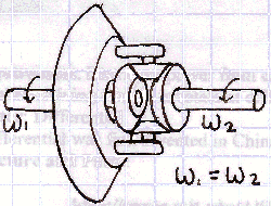 |
| Differential When Car Travels In Straight Line (Wheels at Same Speed) |
When the car is traveling straight, both wheels travel at the same speed. Thus, the free-wheeling planet pinions do not spin at all. Instead, as the transmission shaft turns the crown wheel, the rotary motion is translated directly to the half-shafts, and both wheels spin with the angular velocity of the crown wheel (they have the same speed).
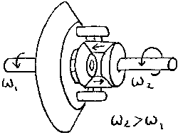 |
| Differential When Car Turns A Corner (Wheels 2 On Outside of Turn) |
When the car is turning, the wheels must move at different speeds. In this situation, the planet pinions spin with respect to the crown wheel as they turn around the sun gears. This allows the speed of the crown gear to be delivered unevenly to the two wheels.
DOMINANT PHYSICS:
Variable |
Description |
Metric Units |
English Units |
v |
Velocity at contact point between gears |
m/sec |
in/sec |
win |
Angular Velocity of Crown gear |
rad/sec |
rev/min |
w1 |
Angular Velocity of one gear/wheel |
rad/sec |
rev/min |
w2 |
Angular Velocity of other gear/wheel |
rad/sec |
rev/min |
r1 |
Pitch radius of one gear |
m |
in |
r2 |
Pitch radius of other gear |
m |
In |
Pin |
Power in, from transmission |
Watts |
Horsepower |
Pout1 |
Power out to Left half-shaft |
Watts |
Horsepower |
Pout2 |
Power out to Right half-shaft |
Watts |
Horsepower |
T1 |
Torque transmitted to Left wheel |
N-m |
ft-lb |
T2 |
Torque transmitted to Right wheel |
N-m |
ft-lb |
N1 |
Number of teeth on one gear |
-- |
-- |
N2 |
Number of teeth on other gear |
-- |
-- |
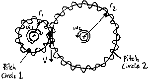 |
| Illustration For Explanation of Gear Ratios |
Ratios: The ratio of speeds between gears is dependent upon the ratio of teeth between the two adjoining gears such that
w1 x N1 = w2 x N2,
where w is the respective angular velocity, and N = the number of teeth on the gear.
Velocity: When two gears are in contact and there is no slipping,
v = w1 x r1 = w2 x r2, where v is the
tangential velocity at the point of contact between the gears, and r is the respective
pitch radius of the gear. In a differential, since the speed transmitted by the crown gear
is shared by both of the wheels (not necessarily traveling at the same speed),
win = (w1 + w2) / 2
Power: Typically, each gear mesh will have 1%-2% loss in efficiency, so with
three different meshes from the transmission shaft to each of the half shafts, the system
will actually be 94% to 97% efficient. In order to simplify things, let us assume that the
system is 100% efficient; then
Pin = Pout1 + Pout2, or Pin = (T1 x w1) + (T2 x w2),
where Pin is the power input from the transmission to the differential, and Pout is the power output from the differential to the wheels. T is the torque supplied to each half-shaft, respectively.
LIMITING PHYSICS:
Things that might limit or disrupt the behavior of the differential include contact stresses between the gears, which limits the torque transmission, as well as fatigue and losses due to friction between the gears.
If one of the wheels attached to a differential decides to hit some ice, for example, it slips and spins with all of the speed the differential has to distribute. Thus, a locking mechanism, or "limited slip differential" allows one wheel to slip or spin freely while some torque is delivered to the other wheel (hopefully on dry land!).
PLOTS/GRAPHS/TABLES:
None Submitted
WHERE TO FIND DIFFERENTIALS:
In the rear axles of most cars and trucks.
REFERENCES/MORE INFORMATION:
http://www.srl.gatech.edu/education/ME3110/design-reports/RSVP/DR4/catalog/gearbas.htm
http://www.ul.ie/~gordons/lavelles/diflimed.html
Macaulay, David. The Way Things Work, pg. 49
Lecture notes, course 2.72