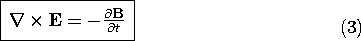
In the MQS approximation, Ampère's law relates the magnetic field intensity H to the current density J.
Augmented by the requirement that H have no divergence, this law was the theme of Chap. 8. Two types of physical situations were considered. Either the current density was imposed, or it existed in perfect conductors. In both cases, we were able to determine H without being concerned about the details of the electric field distribution.
In Chap. 9, the effects of magnetizable materials were represented by the magnetization density M, and the magnetic flux density, defined as B

o (H + M), was found to have no divergence.
Provided that M is either given or instantaneously determined by H (as was the case throughout most of Chap. 9), and that J is either given or subsumed by the boundary conditions on perfect conductors, these two magnetoquasistatic laws determine H throughout the volume.
In this chapter, our first objective will be to determine the distribution of E around perfect conductors. Then we shall broaden our physical domain to include finite conductors, especially in situations where currents are caused by an E that is induced by the time rate of change of B. In both cases, we make explicit use of Faraday's law.
In the EQS systems considered in Chaps. 4-7, the curl of H generated by the time rate of change of the displacement flux density was not of interest. Ampère's law was adequately incorporated by the continuity law. However, in MQS systems, the curl of E generated by the magnetic induction on the right in (1) is often of primary importance. We had fields that depended on time rates of change in Chap. 7.
We have already seen the consequences of Faraday's law in Sec. 8.4, where MQS systems of perfect conductors were considered. The electric field intensity E inside a perfect conductor must be zero, and hence B has to vanish inside the perfect conductor if B varies with time. This leads to n
B = 0 on the surface of a perfect conductor. Currents induced in the surface of perfect conductors assure the proper discontinuity of n x H from a finite value outside to zero inside.
Faraday's law was in evidence in Sec. 8.4 and accounted for the voltage at terminals connected to each other by perfect conductors. Faraday's law makes it possible to have a voltage at terminals connected to each other by a perfect "short." A simple experiment brings out some of the subtlety of the voltage definition in MQS systems. Its description is followed by an overview of the chapter.
Demonstration 10.0.1. Nonuniqueness of Voltage in an MQS System
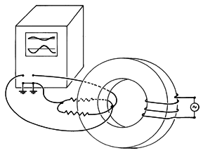
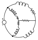
A magnetic flux is created in the toroidal magnetizable core shown in Fig. 10.0.1 by driving the winding with a sinsuoidal current. Because it is highly permeable (a ferrite), the core guides a magnetic flux density B that is much greater than that in the surrounding air.
Figure 10.0.1 A pair of unequal resistors are connected in series around a magnetic circuit. Voltages measured between the terminals of the resistors by connecting the nodes to the dual-trace oscilloscope, as shown, differ in magnitude and are 180 degrees out of phase. Looped in series around the core are two resistors of unequal value, R1
R2. Thus, the terminals of these resistors are connected together to form a pair of "nodes." One of these nodes is grounded. The other is connected to high-impedance voltmeters through two leads that follow the different paths shown in Fig. 10.0.1. A dual-trace oscilloscope is convenient for displaying the voltages.
The voltages observed with the leads connected to the same node not only differ in magnitude but are 180 degrees out of phase.
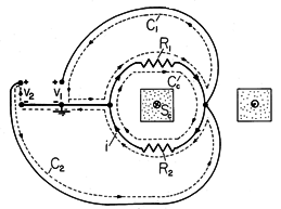
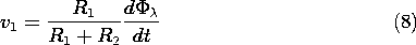
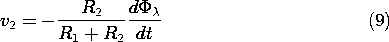
Faraday's integral law explains what is observed. A cross-section of the core, showing the pair of resistors and voltmeter leads, is shown in Fig. 10.0.2. The scope resistances are very large compared to R1 and R2, so the current carried by the voltmeter leads is negligible. This means that if there is a current i through one of the series resistors, it must be the same as that through the other.
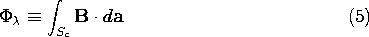
Figure 10.0.2 Schematic of circuit for experiment of Fig. 10.0.1, showing contours used with Faraday's law to predict the differing voltages v1 and v2. The contour Cc follows the closed circuit formed by the series resistors. Faraday's integral law is now applied to this contour. The flux passing through the surface Sc spanning Cc is defined as
. Thus,
where
Given the magnetic flux, (4) can be solved for the current i that must circulate around the loop formed by the resistors.
To determine the measured voltages, the same integral law is applied to contours C1 and C2 of Fig. 10.0.2. The surfaces spanning the contours link a negligible flux density, so the circulation of E around these contours must vanish.
The observed voltages are found by solving (4) for i, which is then substituted into (6) and (7).
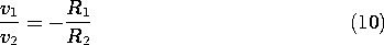
From this result it follows that
Indeed, the voltages not only differ in magnitude but are of opposite signs.
Suppose that one of the voltmeter leads is disconnected from the right node, looped through the core, and connected directly to the grounded terminal of the same voltmeter. The situation is even more remarkable because we now have a voltage at the terminals of a "short." However, it is also more familiar. We recognize from Sec. 8.4 that the measured voltage is simply d
In Sec. 10.1, we begin by investigating the electric field in the free space regions of systems of perfect conductors. Here the viewpoint taken in Sec. 8.4 has made it possible to determine the distribution of B without having to determine E in the process. The magnetic induction appearing on the right in Faraday's law, (1), is therefore known, and hence the law prescribes the curl of E. From the introduction to Chap. 8, we know that this is not enough to uniquely prescribe the electric field. Information about the divergence of E must also be given, and this brings into play the electrical properties of the materials filling the regions between the perfect conductors.
The analyses of Chaps. 8 and 9 determined H in two special situations. In one case, the current distribution was prescribed; in the other case, the currents were flowing in the surfaces of perfect conductors. To see the more general situation in perspective, we may think of MQS systems as analogous to networks composed of inductors and resistors, such as shown in Fig. 10.0.3. In the extreme case where the source is a rapidly varying function of time, the inductors alone determine the currents. Finding the current distribution in this "high frequency" limit is analogous to finding the H-field, and hence the distribution of surface currents, in the systems of perfect conductors considered in Sec. 8.4. Finding the electric field in perfectly conducting systems, the objective in Sec. 10.1 of this chapter, is analogous to determining the distribution of voltage in the circuit in the limit where the inductors dominate.
Figure 10.0.3 Magnetoquasistatic systems with Ohmic conductors are generalizations of inductor-resistor networks. The steady current distribution is determined by the resistors, while the high-frequency response is governed by the inductors. In the opposite extreme, if the driving voltage is slowly varying, the inductors behave as shorts and the current distribution is determined by the resistive network alone. In terms of fields, the response to slowly varying sources of current is essentially the steady current distribution described in the first half of Chap. 7. Once this distribution of J has been determined, the associated magnetic field can be found using the superposition integrals of Chap. 8.
In Secs. 10.2-10.4, we combine the MQS laws of Chap. 8 with those of Faraday and Ohm to describe the evolution of J and H when neither of these limiting cases prevails. We shall see that the field response to a step of excitation goes from a distribution governed by the perfect conductivity model just after the step is applied (the circuit dominated by the inductors), to one governed by the steady conduction laws for J, and Biot-Savart for H after a long time (the circuit dominated by the resistors with the flux linkages then found from