
10.1
Magnetoquasistatic Electric Fields in Systems of PerfectConductors
The distribution of E around the conductors in MQS systems is of engineering interest. For example, the amount of insulation required between conductors in a transformer is dependent on the electric field.
In systems composed of perfect conductors and free space, the distribution of magnetic field intensity is determined by requiring that n
B= 0 on the perfectly conducting boundaries. Although this condition is required to make the electric field tangential to the perfect conductor vanish, as we saw in Sec. 8.4, it is not necessary to explicitly refer to E in finding H. Thus, in Faraday's law of induction, (10.0.3), the right-hand side is known. The source of curl E is thus known. To determine the source of div E, further information is required.
The regions outside the perfect conductors, where E is to be found, are presumably filled with relatively insulating materials. To identify the additional information necessary for the specification of E, we must be clear about the nature of these materials. There are three possibilities:
Although the material is much less conducting than the adjacent "perfect" conductors, the charge relaxation time is far shorter than the times of interest. Thus, /
t is negligible in the charge conservation equation and, as a result, the current density is solenoidal. Note that this is the situation in the MQS approximation. In the following discussion, we will then presume that if this situation prevails, the region is filled with a material of uniform conductivity, in which case E is solenoidal within the material volume. (Of course, there may be surface charges on the boundaries.)
The second situation is typical when the "perfect" conductors are surrounded by materials commonly used to insulate wires. The charge relaxation time is generally much longer than the times of interest. Thus, no unpaired charges can flow into these "insulators" and they remain charge free. Provided they are of uniform permittivity, the E field is again solenoidal within these materials. If the charge relaxation time is on the same order as times characterizing the currents carried by the conductors, then the distribution of unpaired charge is governed by the combination of Ohm's law, charge conservation, and Gauss' law, as discussed in Sec. 7.7. If the material is not only of uniform conductivity but of uniform permittivity as well, this charge density is zero in the volume of the material. It follows from Gauss' law that E is once again solenoidal in the material volume. Of course, surface charges may exist at material interfaces. The electric field intensity is broken into particular and homogeneous parts
where, in accordance with Faraday's law, (10.0.3), and (1),
and
Our approach is reminiscent of that taken in Chap. 8, where the roles of E and
B/
t are respectively taken by H and -J. Indeed, if all else fails, the particular solution can be generated by using an adaptation of the Biot-Savart law, (8.2.7).
Given a particular solution to (3) and (4), the boundary condition that there be no tangential E on the surfaces of the perfect conductors is satisfied by finding a solution to (5) and (6) such that
on those surfaces.
Given the particular solution, the boundary value problem has been reduced to one familiar from Chap. 5. To satisfy (5), we let Eh = -
. It then follows from (6) that
satisfies Laplace's equation.
Example 10.1.1. Electric Field around a Long Coil
What is the electric field distribution in and around a typical inductor? An approximate analysis for a coil of many turns brings out the reason why transformer and generator designers often speak of the "volts per turn" that must be withstood by insulation. The analysis illustrates the concept of breaking the solution into a particular rotational field and a homogeneous conservative field.
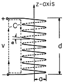
Figure 10.1.1 Side view of long inductor having radius a and length d. Consider the idealized coil of Fig. 10.1.1. It is composed of a thin, perfectly conducting wire, wound in a helix of length d and radius a. The magnetic field can be found by approximating the current by a surface current K that is
directed about the z axis of a cylindrical coodinate system having the z axis coincident with the axis of the coil. For an N-turn coil, this surface current density is K
= Ni/d. If the coil is very long, d
a, the magnetic field produced within is approximately uniform
while that outside is essentially zero (Example 8.2.1). Note that the surface current density is just that required to terminate H in accordance with Ampère's continuity condition.
With such a simple magnetic field, a particular solution is easily obtained. We recognize that the perfectly conducting coil is on a natural coordinate surface in the cylindrical coordinate system. Thus, we write the z component of (3) in cylindrical coordinates and look for a solution to E that is independent of
. The solution resulting from an integration over r is
Because there is no magnetic field outside the coil, the outside solution for Ep is irrotational.
If we adhere to the idealization of the wire as an inclined current sheet, the electric field along the wire in the sheet must be zero. The particular solution does not satisfy this condition, and so we now must find an irrotational and solenoidal Eh that cancels the component of Ep tangential to the wire.
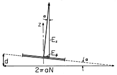
Figure 10.1.2 With the wire from the inductor of Fig. 10.1.1 stretched into a straight line, it is evident that the slope of the wire in the inductor is essentially the total length of the coil, d, divided by the total length of the wire, 2 aN.
A section of the wire is shown in Fig. 10.1.2. What axial field Ez must be added to that given by (10) to make the net E perpendicular to the wire? If Ez and E
are to be components of a vector normal to the wire, then their ratio must be the same as the ratio of the total length of the wire to the length of the coil.
Using (9) and (10) at r = a, we have
The homogeneous solution possesses this field Ez on the surface of the cylinder of radius a and length d. This field determines the potential
h over the surface (within an arbitrary constant). Since
2
h = 0 everywhere in space and the tangential Eh field prescribes
h on the cylinder,
h is uniquely determined everywhere within an additive constant. Hence, the conservative part of the field is determined everywhere.
The voltage between the terminals is determined from the line integral of E
ds between the terminals. The field of the particular solution is
-directed and gives no contribution. The entire contribution to the line integral comes from the homogeneous solution (12) and is
Note that this expression takes the form Ldi/dt, where the inductance L is in agreement with that found using a contour coincident with the wire, (8.4.18).
We could think of the terminal voltage as the sum of N "voltages per turn" Ez d/N. If we admit to the finite size of the wires, the electric stress between the wires is essentially this "voltage per turn" divided by the distance between wires.
The next example identifies the particular and homogeneous solutions in a somewhat more formal fashion.
Example 10.1.2. Electric Field of a One-Turn Solenoid
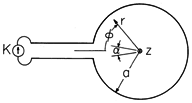
The cross-section of a one-turn solenoid is shown in Fig. 10.1.3. It consists of a circular cylindrical conductor having an inside radius a much less than its length in the z direction. It is driven by a distributed current source K(t) through the plane parallel plates to the left. This current enters through the upper sheet conductor, circulates in the
direction around the one turn, and leaves through the lower plate. The spacing between these plates is small compared to a.
Figure 10.1.3 A one-turn solenoid of infinite length is driven by the distributed source of current density, K(t). As in the previous example, the field inside the solenoid is uniform, axial, and equal to the surface current
and a particular solution can be found by applying Faraday's integral law to a contour having the arbitrary radius r < a, (10).
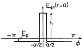
This field clearly does not satisfy the boundary condition at r = a, where it has a tangential value over almost all of the surface. The homogeneous solution must have a tangential component that cancels this one. However, this field must also be conservative, so its integral around the circumference at r = a must be zero. Thus, the plot of the
component of the homogeneous solution at r = a, shown in Fig. 10.1.4, has no average value. The amplitude of the tall rectangle is adjusted so that the net area under the two functions is zero.
The field between the edges of the input electrodes is approximated as being uniform right out to the contacts with the solenoid.
Figure 10.1.4 Tangential component of homogeneous electric field at r = a in the configuration of Fig. 10.1.3. We now find a solution to Laplace's equation that matches this boundary condition on the tangential component of E. Because E
is an even function of
,
is taken as an odd function. The origin is included in the region of interest, so the polar coordinate solutions (Table 5.7.1) take the form
It follows that
The coefficients An are evaluated, as in Sec. 5.5, by multiplying both sides of this expression by cos (m
) and integrating from
= -
to
=
.
Thus, the coefficients needed to evaluate the potential of (17) are
Finally, the desired field intensity is the sum of the particular solution, (15), and the homogeneous solution, the gradient of (17).
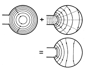
Figure 10.1.5 Graphical representation of solution for the electric field in the configuration of Fig. 10.1.3. The superposition of fields represented in this solution is shown graphically in Fig. 10.1.5. A conservative field is added to the rotational field. The former has a potential at r = a that is a linearly increasing function of
between the input electrodes, increasing from a negative value at the lower electrode at
= -
/2, passing through zero at the midplane, and reaching an equal positive value at the upper electrode at
=
/2. The potential decreases in a linear fashion from this high as
is increased, again passing through zero at
= 180 degrees, and reaching the negative value upon returning to the lower input electrode. Equipotential lines therefore join points on the solenoid periphery with points at the same potential between the input electrodes. Note that the electric field associated with this potential indeed has the tangential component required to cancel that from the rotational part of the field, the proof of this being in the last of the plots.
Often the vector potential provides conveniently a particular solution. With B replaced by
x A,
Suppose A has been determined. Then the quantity in parantheses must be equal to the gradient of a potential
so that
In the examples treated, the first term in this expression is the particular solution, while the second is the homogeneous solution.


