
10.2
Nature of Fields Induced in Finite Conductors
If a conductor is situated in a time-varying magnetic field, the induced electric field gives rise to currents. From Sec. 8.4, we have shown that these currents prevent the penetration of the magnetic field into a perfect conductor. How high must
be to treat a conductor as perfect? In the next two sections, we use specific analytical models to answer this question. Here we preface these developments with a discussion of the interplay between the laws of Faraday, Ampère and Ohm that determines the distribution, duration, and magnitude of currents in conductors of finite conductivity.
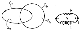
Figure 10.2.1 Current induced in accordance with Faraday's law circulates on contour Ca. Through Ampère's law, it results in magnetic field that follows contour Cb. The integral form of Faraday's law, applied to the surface Sa and contour Ca of Fig. 10.2.1, is
Ohm's law, J =
E, introduced into (1), relates the current density circulating around a tube following Ca to the enclosed magnetic flux.
This statement applies to every circulating current "hose" in a conductor. Let us concentrate on one such hose. The current flows parallel to the hose, and therefore J
ds = J ds. Suppose that the cross-sectional area of the hose is A(s). Then JA(s) = i, the current in the hose, and
is the resistance of the hose. Therefore,
Equation (2) describes how the time-varying magnetic flux gives rise to a circulating current. Ampère's law states how that current, in turn, produces a magnetic field.
Typically, that field circulates around a contour such as Cb in Fig. 10.2.1, which is pierced by J. With Gauss' law for B, Ampère's law provides the relation for H produced by J. This information is summarized by the "lumped circuit" relation
The combination of (4) and (6) provides a differential equation for the circuit current i(t). The equivalent circuit for the differential equation is the series interconnection of a resistor R with an inductor L, as shown in Fig. 10.2.1. The solution is an exponentially decaying function of time with the time constant L/R.
The combination of (2) and (5)- of the laws of Faraday, Ampère, and Ohm- determine J and H. The field problem corresponds to a continuum of "circuits." We shall find that the time dependence of the fields is governed by time constants having the nature of L/R. This time constant will be of the form
In contrast with the charge relaxation time
/
of EQS, this magnetic diffusion time depends on the product of two characteristic lengths, denoted here by l1 and l2. For given time rates of change and electrical conductivity, the larger the system, the more likely it is to behave as a perfect conductor.
Although we will not use the integral laws to determine the fields in the finite conductivity systems of the next sections, they are often used to make engineering approximations. The following demonstration is quantified using rough approximations in a style that typifies how field theory is often applied to practical problems.
Demonstration 10.2.1. Edgerton's Boomer
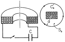
The capacitor in Fig. 10.2.2, C = 25
F, is initially charged to v = 4 kV. The spark gap switch is then closed so that the capacitor can discharge into the 50-turn coil. This demonstration has been seen by many visitors to Prof. Harold Edgerton's Strobe Laboratory at M.I.T.
Figure 10.2.2 When the spark gap switch is closed, the capacitor discharges into the coil. The contour Cb is used to estimate the average magnetic field intensity that results. Given that the average radius of a coil winding a = 7 cm, and that the height of the coil is also on the order of a, roughly what magnetic field is generated? Ampère's integral law, (5), can be applied to the contour Cb of the figure to obtain an approximate relation between the average H, which we will call H1, and the coil current i1.
To determine i1, we need the inductance L11 of the coil. To this end, the flux linkage of the coil is approximated by N1 times the product of the average coil area and the average flux density.
From these last two equations, one obtains
= L11 i1, where the inductance is
Evaluation gives L11 = 0.1 mH.
With the assumption that the combined resistance of the coil, switch, and connecting leads is small enough so that the voltage across the capacitor and the current in the inductor oscillate at the frequency
we can determine the peak current by recognizing that the energy
Cv2 initially stored in the capacitor is one quarter of a cycle later stored in the inductor.
Thus, the peak current in the coil is i1 = 2,000 A. We know both the capacitance and the inductance, so we can also determine the frequency with which the current oscillates. Evaluation gives
= 20 x 103 s-1 (f = 3 kHz).
The H field oscillates with this frequency and has an amplitude given by evaluating (8). We find that the peak field intensity is H1 = 2.3 x 10⁵ A/m so that the peak flux density is 0.3 T (3000 gauss).
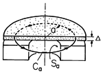
Now suppose that a conducting disk is placed just above the driver coil as shown in Fig. 10.2.3. What is the current induced in the disk? Choose a contour that encloses a surface Sa which links the upward-directed magnetic flux generated at the center of the driver coil. With E defined as an average azimuthally directed electric field in the disk, Faraday's law applied to the contour bounding the surface Sa gives
The average current density circulating in the disk is given by Ohm's law.
Figure 10.2.3 Metal disk placed on top of coil shown in Fig. 10.2.2. If one were to replace the disk with his hand, what current density would he feel? To determine the peak current, the derivative is replaced by
H1. For the hand,

1 S/m and (14) gives 20 mA/cm2. This is more than enough to provide a "shock."
The conductivity of an aluminum disk is much larger, namely 3.5 x 10⁷ S/m. According to (14), the current density should be 35 million times larger than that in a human hand. However, we need to remind ourselves that in using Ampère's law to determine the driving field, we have ignored contributions due to the induced current in the disk.
Ampère's integral law can also be used to approximate the field induced by the current in the disk. Applied to a contour that loops around the current circulating in the disk rather than in the driving coil, (2) requires that
Here, the cross-sectional area of the disk through which the current circulates is approximated by the product of the disk thickness
and the average radius a.
It follows from (14) and (15) that the induced field gets to be on the order of the imposed field when
where
Note that
m takes the form of (7), where l1 =
and l2 = a.
For an aluminum disk of thickness
= 2 mm, a = 7 cm,
m = 6 ms, so
m /4

10, and the field associated with the induced current is comparable to that imposed by the driving coil.
1 As we shall see in the next sections, because the calculation is not self-consistent, the inequalitym
1 indicates that the induced field is comparable to and not in excess of the one imposed.
The surface of the disk is therefore one where n
B
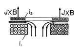
0. The lines of magnetic flux density passing upward through the center of the driving coil are trapped between the driver coil and the disk as they turn radially outward. These lines are sketched in Fig. 10.2.4.
In the terminology introduced with Example 9.7.4, the disk is the secondary of a transformer. In fact,
m is the time constant L22/R of the secondary, where L22 and R are the inductance and resistance of a circuit representing the disk. Indeed, the condition for ideal transformer operation, (9.7.26), is equivalent to having
m/4

1. The windings in power transformers are subject to the forces we now demonstrate.
If an aluminum disk is placed on the coil and the switch closed, a number of applications emerge. First, there is a bang, correctly suggesting that the disk can be used as an acoustic transducer. Typical applications are to deep-sea acoustic sounding. The force density F (N/m3) responsible for this sound follows from the Lorentz law (Sec. 11.9)
Note that regardless of the polarity of the driving current, and hence of the average H, this force density acts upward. It is a force of repulsion. With the current distribution in the disk represented by a surface current density K, and B taken as one half its average value (the factor of 1/2 will be explained in Example 11.9.3), the total upward force on the disk is
By Ampère's law, the surface current K in the disk is equal to the field in the region between the disk and the driver, and hence essentially equal to the average H. Thus, with an additional factor of
to account for time averaging the sinusoidally varying drive, (19) becomes
In evaluating this expression, the value of H adjacent to the disk with the disk resting on the coil is required. As suggested by Fig. 10.2.4, this field intensity is larger than that given by (8). Suppose that the field is intensified in the gap between coil and plate by a factor of about 2 so that H
5 x 10⁵ A. Then, evaluation of (20) gives 103 N or more than 1000 times the force of gravity on an 80 g aluminum disk. How high would the disk fly? To get a rough idea, it is helpful to know that the driver current decays in several cycles. Thus, the average driving force is essentially an impulse, perhaps as pictured in Fig. 10.2.5 having the amplitude of (20) and a duration T = 1 ms. With the aerodynamic drag ignored, Newton's law requires that
where M = 0.08 kg is the disk mass, V is its velocity, and uo (t) is the unit impulse. Integration of this expression from t = 0- (when the velocity V = 0) to t = 0+ gives
Figure 10.2.4 Currents induced in the metal disk tend to induce a field that bucks out that imposed by the driving coil. These currents result in a force on the disk that tends to propel it upward. Figure 10.2.5 Because the magnetic force on the disk is always positive and lasts for a time T shorter than the time it takes the disk to leave the vicinity of the coil, it is represented by an impulse of magnitude foT. For the numbers we have developed, this initial velocity is about 10 m/s or about 20 miles/hr. Perhaps of more interest is the height h to which the disk would be expected to travel. If we require that the initial kinetic energy
MV2 be equal to the final potential energy Mgh (g = 9.8 m/s2), this height is
V2/g
5 m.
The voltage and capacitance used here for illustration are modest. Even so, if the disk is thin and malleable, it is easily deformed by the field. Metal forming and transport are natural applications of this phenomenon.


