
11.4
Energy Storage
In the conservation theorem, (11.2.7), we have identified the terms E

P/
t and H


o M /
t as the rate of energy supplied per unit volume to the polarization and magnetization of the material. For a linear isotropic material, we found that these terms can be written as derivatives of energy density functions. In this section, we seek a more general description of energy storage. First, nonlinear materials are considered from the field viewpoint. Then, for those systems that can be described in terms of electrical terminal pairs, energy storage is formulated in terms of terminal variables. We will find the results of this section directly applicable to finding electric and magnetic forces in Secs. 11.6 and 11.7.
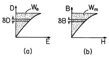
Figure 11.4.1 Single-valued constitutive laws showing energy density associated with variables at the endpoints of the curves: (a) electric energy density; and (b) magnetic energy density.
Energy Densities
Consider a material in which E and D(
o E + P) are collinear. With E and D representing the magnitudes of these vectors, this material is presumed to be described by a constitutive law in which E is a single-valued function of D, such as that sketched in Fig. 11.4.1a. In the case of a linear constitutive law, the curve is a straight line with a slope equal to the permittivity
.
Consider a material in which E and P are collinear (isotropic material). Then, of course, E and D

o E + P are collinear as well. One may graph the magnitude of D versus E and obtain a complete characterization of the material. Now the power per unit volume imparted to the polarization is E

P/
t. If one adds to it the rate of energy supply to the field per unit volume (the free space part) E

oE/
t, one obtains for the power per unit volume
The power supplied to the unit volume can now be written as the time derivative of a function of D, We(D). Indeed, if we define the area above the graph in Fig. 11.4.1 as We, then
Thus, E (
D/
t) is the derivative of the function We(D). This function is the energy stored per unit volume, because the energy supplied per unit volume expressed by the integral
is a function of the final value D of the displacement flux, and we assumed that the fields E and D were zero at t = -
. Here,
D represents the differential of D, usually denoted by dD. We will use
rather than d to avoid confusion between differentials used in carrying out volume, surface and line integrals and the differential used here, which implies an integration in a "state space" having the "dimension" D.
Similar arguments show that if B

o (H + M) and H are collinear, and if H is a single-valued function of B, then
where
With (1) and (4) replacing the first four terms on the right in the energy theorem of (11.2.7), it is clear that the energy density W = We + Wm. The electric and magnetic energy densities have the geometric interpretations as areas on the graphs representing the constitutive laws in Fig. 11.4.1.
Energy Storage in Terms of Terminal Variables
It was shown in Sec. 11.3 that the power input to a system could be represented by the sum of the vi products for each of the terminal pairs, (11.3.29), provided certain conditions were met in the neighborhoods of the terminals. The description of energy storage in a loss-free system in terms of terminal variables will be found useful in determining electric and magnetic forces. With the assumption that all of the power input to a system is accounted for by a time rate of change of the energy stored, the energy conservation statement for a system becomes
where
and the integral is carried over the volume of the system. If the system is electroquasistatic, conservation of charge requires that the terminal current be the time rate of change of the charge on the electrode to which the positive terminal is attached.
Further, w = we, the stored electric energy. Thus, one concludes from (6) that
The second expression states that with the addition of an incremental amount of charge dqi to an electrode having the voltage vi goes an incremental change in the stored energy we. Integration on the charges then gives the total energy
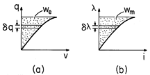
Figure 11.4.2 Single-valued terminal relations showing total energy stored when variables are at the endpoints of the curves: (a) electric energy storage; and (b) magnetic energy storage. To complete this integral, each of the terminal voltages must be a known function of the associated charges.
Integration is then carried out along any path in the state space (q1
qn) that begins at the origin and ends with the desired charges on the electrodes (and hence the desired terminal voltages). For a single terminal pair, the energy can be pictured as the area shown in Fig. 11.4.2a.
If the system is magnetoquasistatic, the conservation law for a lossless system that can be described by terminal relations again takes the form of (6). However, rather than expressing the currents as derivatives of electrode charges, the voltages are derivatives of the fluxes linked by the respective terminal pairs.
Then, (6) leads to
To complete this integral, we require the terminal currents as functions of the terminal flux linkages.
For a single terminal pair system, wm is portrayed in Fig. 11.4.2b.
The most general way to compute the total energy stored in a system is to integrate the energy densities given by (3) and (5) over the volumes of the respective systems. If systems can be described in terms of terminal relations and are loss free, (9) and (12) must lead to the same answers. Note that (D, E) and (q, v) are the field and circuit variables in the EQS systems, while (B, H) and (
,i) have corresponding roles in MQS systems.
Example 11.4.1. An Electrically Linear System
A dielectric slab of permittivity
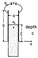
partially fills the region between plane parallel perfectly conducting electrodes, as shown in Fig. 11.4.3. With the fringing field ignored, we find the total energy stored by two methods. First, the energy density is integrated over the volume. Then, the terminal relation is used to evaluate the total energy.
Figure 11.4.3 Capacitor partially filled by free space and by dielectric having permittivity .
An exact solution for the electric field well between the electrodes is simply E =ix (v/a). Note that this field satisfies the boundary conditions at the interface between the dielectric slab and the free space region above and at the electrodes. We assume that a
b and therefore neglect the fringing fields.
The energy density in the linear dielectric, where D =
E, follows from evaluation of (3).
In the free space region, the same result applies with


o.
Integration of these energy densities over the regions in which they apply amounts to a multiplication by the respective volumes. Thus, the total energy is
Note that this expression takes the form
where
In terms of the terminal variables, where q = Cv, the total energy follows from an evaluation of (9).
Once the integration has been carried out, the last expression is written by again using the relation q = Cv. Note that the volume integration of the energy density and the integration in terms of the terminal variables give the same result.
The next example considers an MQS system with two terminal pairs and thus illustrates the integration called for in evaluating the energy from the terminal relations. Also, the energy stored in coupled inductors is often of practical interest.
Example 11.4.2. Coupled Coils; Transformers
An example of a two terminal pair lossless MQS system is a pair of coupled coils having the terminal relations
In this case, (12) becomes
To evaluate this expression, we need to substitute for the currents written in terms of the flux linkages. This requires the inversion of (18). For linear systems, this is easily done, but not for nonlinear systems. To avoid inversion, we rewrite the right-hand side of (19), which becomes
and regroup terms
where the coenergy is defined as
Equation (21) can be integrated when the flux linkages are expressed in terms of the currents, and that is the form in which the terminal relations are given by (18). Once the coenergy wm' has been found, wm follows from (22).
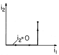
Figure 11.4.4 Integration path in state space consisting of terminal currents.
The integration of (19) is a line integral in a state space (i1, i2). If energy is conserved, we must be able to carry out this integration along any path that begins with the currents turned off and ends with the currents at the desired values. In the path represented by Fig. 11.4.4, the current i1 is turned up first while holding the current i2 to zero. Then, with i1 held fixed at its final value, the current i2 is raised from zero to its final value. For this path, the integration of (22) becomes
Substitution for the flux linkages from (18) and evaluation of the integrals then gives
If the integration is carried out along a path where the roles of i1 and i2 are reversed, the expression obtained is (24) with L12
L21. To make the energy stored independent of path, the mutual inductances must be equal.
This relation, which we found to hold for the transformer of Example 9.7.4, is required if energy is to be conserved. The energy is now evaluated by substituting this expression and the flux linkages expressed using (18) into (22) solved for wm. It follows that
Evaluation of the energy stored in a unity-coupled transformer, where the inductances take the form of (9.7.20), gives
Operating under "ideal" conditions [in the sense that i2/i1 = -N1/N2, (9.7.13)], the transformer does not store energy, wm = 0. Thus, according to the power theorem in the form of (6), under ideal operating conditions, the power input at one terminal pair instantaneously appears as a power output at the second terminal pair.
Examples have so far involved linear polarization and magnetization constitutive laws. In the following, the EQS energy storage in a material having a nonlinear polarization constitutive law is determined.
Example 11.4.3. Energy Storage in Electrically Nonlinear Material
To represent the tendency of the polarization to saturate as the electric field is raised, a constitutive law might take the form
Here,
1 and
2 are parameters descriptive of the specific material, and D is collinear with E. This constitutive law is portrayed graphically in Fig. 11.4.5.
Because D is given as a function of E that is not easily solved for E as a function of D, the computation of the electric energy density using (3) is inconvenient. However, we can observe that
and then regroup terms so that the expression becomes
where
Integration now leads to the coenergy density We', but the energy density We can then be found using (31) and the constitutive law.
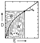
Specifically, evaluation of (30) using (28) gives the coenergy density
It follows from (31) that the energy density is
Figure 11.4.5 Single-valued nonlinear constitutive law. Areas representing energy density W and coenergy density W' are not equal in this case. A graphical representation of the energy and coenergy functions is given in Fig. 11.4.5. The area "under the curve" with D as the integration variable is We, (3), and the area under the curve with E as the integration variable is We', (31).
