
11.6
Electrical Forces on Macroscopic Media
Electrical forces on macroscopic materials have their origins in the forces exerted on the microscopic particles of which the materials are composed. Macroscopic fields have been used to describe conduction, polarization, and magnetization. In Chaps. 6, 7 and 9, polarization, current, and magnetization densities, respectively, were related to the macroscopic field variables through constitutive laws. Typically, the parameters in these laws are determined from measurements. Thus, the experimentally determined relations make it unnecessary to take detailed account of how the microscopic fields are averaged.
Because the definition of the average is already implicit in our macroscopic formulation of Maxwell's equations, we must now take care that our use of macroscopic field quantities for representing electromagnetic forces is self-consistent. The force on a macroscopic volume element
V of a material is the sum of the forces on the charged particles and magnetic dipoles constituting the material. Consider the simple case in which no magnetic dipoles are present. Then
where the summation is over all the charges within
V at their respective positions. Now, the fields E(ri) and H(ri) are the microscopic fields that vary greatly from point ri to point rj in the material. The macroscopic fields E(r) and H(r) are averaged (smoothed) versions of these fields, whose sources are the averaged charge densities
and
where the velocity vi of the microscopic particles should be distinguished from that of the macroscopic material in which they are embedded or through which they move. The average of a product is not equal to the product of the averages. Thus, one could not find the force density F = f/
V from the expression
E + J x
o H, as the product of the averaged charge density and averaged electric field plus averaged current density times averaged magnetic flux density. Other methods have to be used to determine the force. One of the most useful is the energy method. Given the constitutive law for the material, which represents the interrelationship between macroscopic field variables, conservation of energy provides a way of deducing the self-consistent force acting on the material.
In this and the next section, we illustrate how total forces can be determined using conservation of energy as a premise. In this section, the EQS systems considered have only one mechanical degree of freedom and only one electrical terminal pair. In the next section, MQS systems are considered and the approach is broadened to a somewhat more general class of systems. A parallel approach determines the force density rather than the total force. After expanding on microscopic forces in Sec. 11.8, we shall review macroscopic force densities in Sec. 11.9.
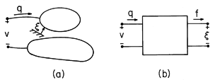
Figure 11.6.1 (a) Electroquasistatic system having one electrical terminal pair and one mechanical degree of freedom. (b) Schematic representation of EQS subsystem with coupling to external mechanical system represented by a mechanical terminal pair. Typical of the electroquasistatic problems considered in this section is the pair of metallic electrodes shown in Fig. 11.6.1. With the application of a voltage, unpaired charges of opposite polarity are induced on the electrode surfaces. The electrical state of the system is specified by giving the geometry and the potential difference v between the electrodes. Here we picture one electrode as movable, with its position denoted by
. The two terminal pair system of Fig. 11.6.1b is useful to include mechanical effects via an additional terminal pair. If we think of the net unpaired charge q on the electrode as an electrical terminal variable complementing v, then the force of electrical origin f complements the mechanical displacement
.
Given the electrical terminal relation v = v(q,
), we now use an energy conservation principle to determine the force f = f(q,
) that acts to increase the displacement
. The electrical terminal relation can either be regarded as a measured function or be predicted using the macroscopic field laws and constitutive laws for the materials within the "box."
It is now assumed that there is no conversion of electrical energy to thermal form within the box of Fig. 11.6.1b. Mechanisms for conversion of energy to heat are modeled by elements outside the box. For example, the finite conductivity of any dielectric is taken into account by a resistance external to the system. Thus, the electrical power input to what is defined as the "box," the electroquasistatic subsystem, must either result in a change in the electrical energy stored or mechanical power expended as the force f acts on the mechanical system. The integral form of the power conservation theorem, (11.1.1), is generalized to include the rate of work by the force f
In Sec. 11.4, we represented the quasistatic net electrical power input on the left in this expression in circuit theory terms. With the total energy we defined as the integral of the energy density over the entire volume of the system, (4) becomes
where the electrical power input is the product vi = vdq/dt. Multiplication of (4) by dt converts a statement of power flow to one of energy conservation.
If an increment of charge dq is placed on an electrode at potential v, an increment of energy vdq is added to the system that produces a change in the total stored energy dwe, an increment of work fd
done on an external mechanical system, or some combination of both. Here, f(q,
) is the as yet unknown force. Solved for dwe, this energy conservation statement is
This expression describes what might be termed a quasistatic electrical and mechanical subsystem. The state of this subsystem is specified by prescribing the geometry (
) and the charge on the electrode, for then the voltage of the electrode follows from the terminal relation v(q,
). The state of the subsystem is fully determined by the variables (q,
), which are therefore regarded as independent variables. In terms of the two terminal pairs shown in Fig. 11.6.1b, one of each pair of terminal variables has been chosen as an independent variable.
The incremental change in we (q,
) associated with incremental changes of dq and d
in the independent variables is
Because q and
can be independently specified, (7) and (8) must hold for any combination of dq and d
. For example, they must hold if the position of the electrode is held fixed so that d
= 0 and the charge is changed by the incremental amount dq. They must also describe the change in energy resulting from making an incremental displacement d
of the electrode under open circuit conditions, where dq = 0. Indeed, (7) and (8) hold if q and
are changed by arbitrary incremental amounts, and so it follows that the coefficients of dq in (7) and (8) must be equal to each other, as must the coefficients of d
.
(9)
Given the total energy, written in terms of the independent variables (q,
), the second of these relations provides the desired force. Integration of the energy density over the volume of the system is one way to determine we. Another is to integrate (7) along a line in the state space (q,
) designed so that the integral can be carried out without having to know f.
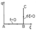
Figure 11.6.2 Path of line integration in state space (q, ) used to find energy at location C.
Such a path4 is shown in Fig. 11.6.2, where it is assumed that the force of electrical origin f is zero if the charge q is zero. Thus, in integrating along the contour q = 0 from A
B, dq = 0 and f = 0, so there is no contribution.
4 Note the analogy with the line integral
 (Ex dx + Ey dy) of a two-dimensional conservation field that
results in the potential
  (x, y).
The remainder of the integral, from BC, is carried out with
fixed, so d
= 0, and (10) reduces to
We have accounted for the energy required to place the subsystem in the state (q,
). In physical terms, the mathematical steps represent first assembling the subsystem mechanically with no electrical excitation. Because there is no force acting on the electrode as it is put in place, no work is involved. Then, with its location fixed, the electrode is charged by means of an electrical source.
Suppose that the subsystem is electrically linear, so that either as a result of mathematical modeling or of measurements on the actual system, the electrical terminal relation takes the form
Then, with this relation used to evaluate (11), it follows that the energy is
Finally, the desired force of electrical origin follows from substituting this expression into (9b).
Note that with a similar substitution into (9a), the terminal relation of (12) is obtained.
Once the partial derivative with respect to
has been taken while holding the proper independent variable (q) fixed, the force can be written in terms of variables other than the independent ones. Thus, with the use of the terminal relation, (12), the force is written in terms of the terminal voltage v as
The following example gives the opportunity to apply this result to a specific configuration.
Example 11.6.1. Force on a Capacitor Plate
The region between the plane parallel electrodes shown in Fig. 11.6.3 is filled by a layer of dielectric having permittivity
and thickness b and an air gap
. The total distance between electrodes, b +
, is small compared to the linear dimensions of the plates, so fringing fields will be ignored. Thus, the electric fields Ea and Eb in the air gap and in the dielectric, respectively, are uniform. What force on the upper electrode results from applying the voltage v between the electrodes?
Figure 11.6.3 Specific example of EQS systems having one electrical and one mechanical terminal pair. First we determine the charge q on the upper electrode. To this end, the integral of E from the upper electrode to the lower one must be equal to the applied voltage, so
Further, there is presumably no unpaired surface charge at the interface between the dielectric layer and the air gap. Thus, Gauss' continuity condition requires that
Elimination of Eb between these equations gives
In terms of this electric field at the surface of the upper electrode, Gauss' continuity condition shows that the total charge on the upper electrode is
and so it follows from (18) that the electrical terminal relation can be written in terms of a capacitance C.
Because the dielectric is described by a linear constitutive law, we have obtained an electrical terminal relation where v is a linear function of q.
The force acting on the upper electrode follows from a substitution of (20) into (15).
By definition, if f is positive, it acts in the direction of
. Here we find that regardless of the polarity of the applied voltage, f is negative. This is to be expected, because charges of one polarity on the upper electrode are attracted toward those of opposite polarity on the lower electrode.
In describing energy conversion, a minus sign can be extremely important. For example, vdq is the incremental energy into the electroquasistatic subsystem, while f d
is the energy leaving that subsystem as the force of electrical origin acts on the external mechanical system. Thus, if f is positive, it acts on the mechanical system in such a direction as to increase the associated displacement.
Rotating motors and generators are examples where the conversion of energy between electrical and mechanical form is a cyclic process. In these cases, the subsystem returns to its original state once each cycle. The energy converted per cycle is determined by integrating the energy conservation law, (6), around the closed path in the state space representing this process.
Because the energy stored in the system must return to its original value, there is no net contribution of the energy storage term in (22). For a cyclic process, the net electrical energy input per cycle must be equal to the net mechanical power output per cycle.
The following demonstration is primarily intended to give further insight into the implications of the conservation of energy principle for a cyclic process.
Demonstration 11.6.1. An Energy Conversion Cycle
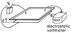
The experiment shown in Fig. 11.6.4 is based on the plane parallel capacitor configuration analyzed in Example 11.6.1. The lower electrode, aluminum foil mounted on a table top, is covered by a thin sheet of plastic. The upper one is also foil, but taped to an insulating sheet which is attached to a frame. This electrode can then be manually raised and lowered to effectively control the displacement
.
Figure 11.6.4 Apparatus used to demonstrate amplification of voltage as the upper electrode is raised. (The electrodes are initially charged and then the voltage source is removed so q = constant.) The electrodes, consisting of foil mounted on insulating sheets, are about 1 m x 1 m, with the upper one insulated from the frame, which is used to control its position. The voltage is measured by the electrostatic voltmeter, which "loads" the system with a capacitance that is small compared to that of the electrodes and (at least on a dry day) a negligible resistance. With the letters A through D used to designate states of the system, we consider the following energy conversion cycle.
If the terminals are again open (i = 0) but the A B. With v = 0, the upper electrode rests on the plastic sheet. A voltage Vo is applied.
B C. With the voltage source removed so that the upper electrode is electrically isolated, it is raised to the position
= L.
C D. The upper electrode is shorted, so that its voltage returns to zero.
D A. The upper electrode is returned to its original position at
= 0.
Is electrical energy converted to mechanical form, or vice versa?
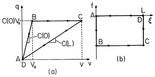
Figure 11.6.5 Closed paths followed in cyclic conversion of energy from mechanical to electrical form: (a) in (q, v) plane; and (b) in (f, ) plane.
The process in carrying out the closed integrals on the left-hand and right-hand sides of (23) as the cycle is carried out can be pictured in the (q, v) and (f,
) planes, respectively, as shown in Fig. 11.6.5. From A
B, q = C(0)v, where C(
) is given by (20). Thus, the trajectory in the (q, v) plane is a straight line ending at the voltage v = Vo of the source. Because the upper electrode has remained at its original position, the trajectory in the (f,
) plane is along the
= 0 axis. The force on the electrode caused by raising its voltage to Vo follows from (21).
Now, from B
C, the voltage source is removed so that as the upper electrode is raised to
= L, its charge is conserved. This means that the trajectory in the (q, v) plane is one where q = constant = Vo C(0). The voltage reached by the upper electrode can be found by requiring that q be conserved.
In the experiment, the thickness b of the dielectric sheet is a fraction of a millimeter, while the final elevation
= L might be 20 cm. (If the displacement is larger than this, the fringing field comes into play and the expression for the capacitance is no longer valid.) Thus, as the sheet is raised, an original voltage of 500 V is easily amplified to 10 - 20 kV. This is readily observed by means of an electrostatic voltmeter attached to the upper electrode, as shown in Fig. 11.6.4.
To determine the trajectory B
C in the (f,
) plane, observe from (14) or (24) that as a function of q, the force is independent of
.
The trajectory B
C in the (f,
) plane is therefore one of constant fB given by (24). In general, f(q,
) is not independent of
, but in plane parallel geometry, it is.
The system is now returned to its original state in two steps. First, from C
D, the upper electrode remains at
= L and is shorted to ground. In the (q, v) plane, the state returns to the origin along the straight line given by q = C(L)v, (20). In the (f,
) plane, the force drops to zero with
= L. Second, from D
A, the upper electrode is returned to its original position. The values of (q, v) remain zero, while the trajectory in the (f,
) plane is f = 0.
The experiment is simple enough so that we can use physical reasoning to decide the direction of energy conversion. Although the force of gravity is likely to exceed the electrical force of attraction between the electrodes, as far as the electrical subsystem is concerned, the upper electrode is raised against a downward electrical force. Because the charge is removed before it is lowered, there is no electrical force on the electrode as it is lowered. Thus, net work is done on the EQS subsystem. The right-hand side of (23), the net work done by the subsystem on the external mechanical system, is thus negative.
Evaluation of one or the other of the two sides of the energy conversion law, (23), provides two other ways to determine the direction of energy conversion. Consider first the electrical input energy. The integral has contributions from A
B (where the source is used to charge the upper electrode) and from C
D (where the electrode is discharged). The areas under the respective triangles representing the integral of vdq are
In view of the expression for C(
), (20), this expression can be written as
This expression is clearly negative, indicating that the net electrical energy flow is out of the electrical terminal pair. This is consistent with having a net mechanical energy input to the system.
The net mechanical output energy per cycle expressed by the right-hand side of (23) should be equal to (28). To see that this is so, we recognize that the integral consists of two possible contributions, from B
C and D
A. During the latter, f = 0, so the magnitude of the integral is simply the area of the rectangle in Fig. 11.6.5b.
As required by the conservation law, this mechanical energy output is negative and is equal to the net electrical input energy given by (28).
With the sequence of electrical and mechanical terminal constraints described above, there is a net conversion of energy from mechanical to electrical form. The system acts as an electrical generator with energy provided by whoever raises and lowers the upper electrode. With the voltage applied when the electrode is at its largest displacement, and the electrode grounded before it is raised, the energy flow is from the electrical voltage source to the mechanical system. In this case, the system acts as a motor. We will have the opportunity to exemplify a practical motor in the next section. Most motors are MQS rather than EQS. However, a practical EQS device that is designed to convert energy from mechanical to electrical form is the capacitor microphone, a version of which was described in Example 6.3.3.
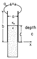
Electrical forces have their origins in forces on unpaired charges and on dipoles. The force on the upper capacitor plate of Example 11.6.1 is due to the unpaired charges. The equal and opposite force on the combination of electrode and dielectric is in part due to unpaired charges and in part to dipoles induced in the dielectric. The following exemplifies a total force that is entirely due to polarization.
Example 11.6.2. Force on a Dielectric Material
We return to the configuration of Example 11.4.1, where a dielectric slab extends a distance
into the region between plane parallel electrodes, as shown in Fig. 11.6.6. The capacitance was found in Example 11.4.1 to be (11.4.16).
It follows from (15) that there is a force tending to draw the dielectric into the region between the electrodes.
This force results because dipoles induced by the fringing field experience forces in the
direction that are passed on to the material in which they are embedded. Even though the force is due to the fringing fields, the net force does not depend on the details of that field. This is evident from our energy arguments because, at least as long as the upper edge of the slab is well within the region between the plates and the lower edge never reaches the vicinity of the electrodes, the energy storage in the fringing fields does not change when the slab is moved.
Figure 11.6.6 Slab of dielectric partially extending between capacitor plates. The spacing, a, is much less than either b or the depth c of the system into the paper. Further, the upper surface at is many spacings a away from the upper and lower edges of the capacitor plates, as is the lower surface as well.
Further discussion of the force density responsible for the force on the dielectric will be given in Sec. 11.9. Its physical reality is demonstrated next.
Demonstration 11.6.2. Force on a Liquid Dielectric
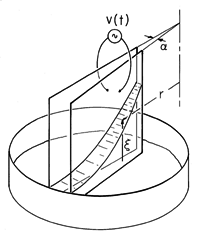
In the experiment shown in Fig. 11.6.7, capacitor plates are dipped into a dish full of dielectric liquid. Thus, with the application of the voltage, it rises against gravity. To demonstrate the relationship between the voltage and the force, the spacing between the electrodes is a slowly varying function of radial position. With r denoting the radial distance from an axis where an extension of the electrodes would join, and
the angle between the electrodes, the spacing at a distance r is
r. Thus, in (31), the spacing between electrodes a

r and the force per unit radial distance tending to push the liquid upward is a function of the radial position.
Figure 11.6.7 In a demonstration of the polarization force, a pair of conducting transparent electrodes are dipped into a liquid (corn oil dyed with food coloring). They are closer together at the upper right than at the lower left, so when a voltage is applied, the electric field intensity decreases with increasing distance, r, from the apex. As a result, the liquid is seen to rise to a height that varies as 1/r2. The electrodes are about 10 cm x 10 cm, with an electric field exceeding the nominal breakdown strength of air at atmospheric pressure, 3 x 10⁶ V/m. The experiment is therefore carried out under pressurized nitrogen.
This force must raise a column of liquid having a height
and width
r. With the mass density of the liquid defined as
, the total mass per radial distance raised by this force is therefore
r

. Force equilibrium is therefore represented by setting the force per unit radial length equal to this mass multiplied by the gravitational acceleration g.
This expression can be solved for
(r).
In the experiment,
5See film Electric Fields and Moving Media from series by National Committee for Electrical Engineering Films, Education Development Center, 39 Chapel St., Newton, Mass. 02160. the electrodes are constructed from tin-oxide coated glass. They are then both conducting and transparent. As a result, the height to which the liquid rises can be seen to obey (34), both as to its magnitude and its radial dependence on r.
To obtain an appreciable rise of the liquid without exceeding the field strength for electrical breakdown between the electrodes, the atmosphere over the liquid must be pressurized. Also, to avoid effects of unpaired charges injected at high field strengths by the electrodes, the applied voltage is alternating and, because the force is proportional to the square of the applied field, the height of rise is proportional to the rms value of the voltage.


