
12.6
Periodic Sheet-Source Fields: Uniform and Nonuniform PlaneWaves
This section introduces the electrodynamic fields associated with surface sources. The physical systems analyzed are generalizations, on the one hand, of such EQS situations as Example 5.6.2, where sinusoidal surface charge densities produced a Laplacian field decaying away from the surface charge source. On the other hand, the MQS sinusoidal surface current sources producing magnetic fields that decay away from their source (for example, Prob. 8.6.9) are generalized to the fully dynamic case. In both cases, one expects that the quasistatic approximation will be contained in the limit where the spatial period of the source is much smaller than the wavelength
= 2
/
. When the spatial period of the source approaches, or exceeds, the wavelength, new phenomena ought to be revealed. Specifically, distributions of surface current density K and surface charge density
s are given in the x - z plane.
These are independent of z and are typically periodic in space and time, extending to infinity in the x and z directions.
Charge conservation links K and
s. A two-dimensional version of the charge conservation law, (12.1.22), requires that there must be a time rate of decrease of surface charge density
s wherever there is a two-dimensional divergence of K.
The second expression results because Kz is independent of z.
Under the assumption that the only sources are those in the x - z plane, it follows that the fields can be pictured as the superposition of those due to (Kx,
s) given to satisfy (3) and due to Kz. It is therefore convenient to break the fields produced by these two kinds of sources into two categories.
Transverse Magnetic (TM) Fields
The source distribution (Kx,
s) does not produce a z component of the vector potential A, Az = 0. This follows because there is no z component of the current in the superposition integral for A, (12.3.2). However, there are both current and charge sources, so that the superposition integral for
requires that in addition to an A that lies in x - y planes, there is an electric potential as well.
Because the source distribution is independent of z, we have taken these potentials to be also two dimensional. It follows that H is transverse to the x - y coordinates upon which the fields depend, while E lies in the x - y plane.
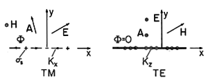
Sources and fields for these transverse magnetic (TM) fields have the relative orientations shown in Fig. 12.6.1.
Figure 12.6.1 Transverse magnetic and electric sources and fields. We will be concerned here with sources that are in the sinusoidal steady state. Although A and
could be used to derive the fields, in what follows it is more convenient to deal directly with the fields themselves. The complex amplitude of Hz, the only component of H, is conveniently used to represent E in the free space regions to either side of the sheet. This can be seen by using the x and y components of Ampère's law to write
for the only two components of E.
The relationship between H and its source is obtained by taking the curl of the vector wave equation for A, (12.1.8). The curl operator commutes with the Laplacian and time derivative, so that the result is the inhomogeneous wave equation for H.
For the sheet source, the driving term on the right is zero everywhere except in the x - z plane. Thus, in the free space regions, the z component of this equation gives a differential equation for the complex amplitude of Hz.
This expression is a two-dimensional example of the Helmholtz equation. Given sinusoidal steady state source distributions of (Kx,
s) consistent with charge conservation, (3), the continuity conditions can be used to relate these sources to the fields described by (6), (7), and (9).
Product Solutions to the Helmholtz Equation
One theme of this section is the solution to the Helmholtz equation, (9). Note that this equation resulted from the time-dependent wave equation by separation of variables, by assuming solutions of the form Hz (x, y) T(t), where T(t) = exp (j
t). We now look for solutions expressing the x - y dependence that take the product form X(x) Y(y). The process is familiar from Sec. 5.4, but the resulting family of solutions is of wider variety, and it is worthwhile to focus on their nature before applying them to particular examples.
With the substitution of the product solution Hz = X(x) Y(y), (9) becomes
This expression is satisfied if the first and second terms are constants
and it follows that parts of the total solution are governed by the ordinary differential equations
Although kx and ky are constants, as long as they satisfy (11) they can be real or imaginary. In this chapter, we are interested in solutions that are periodic in the x direction, so we can think of kx as being real and kx2 > 0. Furthermore, the value of kx is fixed by the assumed functional form of the surface currents and charges. Equation (11) then determines ky from given values of kx and
. In solving (11) for ky, we must take the square root of a quantity that can be positive or negative. By way of distinguishing the two roots of (11) solved for ky, we define
13 and write the two solutions to (11) as
Thus,
is defined as either positive real or negative imaginary, and what we have found for the product solution X(x) Y(y) are combinations of products
Note that if
2
< kx2, ky is defined by (13) and (14) such that the field, which is periodic in the x direction, decays in the +y direction for the upper solution but decays in the -y direction for the lower solution. These fields resemble solutions to Laplace's equation. Indeed, in the limit where
2

kx2, the Helmholtz equation becomes Laplace's equation.
As the frequency is raised, the rate of decay in the
y directions decreases until ky becomes real, at which point the solutions take a form that is in sharp contrast to those for Laplace's equation. With
2
> kx2, the solutions that we assumed to be periodic in the x direction are also periodic in the y direction.
The wave propagation in the y direction that renders the solutions periodic in y is more evident if the product solutions of (15) are written with the time dependence included.
For
2
> kx2, the upper and lower signs in (16) [and hence in (14)] correspond to waves propagating in the positive and negative y directions, respectively.
By taking a linear combination of the trigonometric functions in (16), we can also form the complex exponential exp (jkx x). Thus, another expression of the solutions given by (16) is as
Instead of having standing waves in the x direction, as represented by (16), we now have solutions that are traveling in the
x directions. Examples 12.6.1 and 12.6.2, respectively, illustrate how standing-wave and traveling-wave fields are excited.
Example 12.6.1. Standing-Wave TM Fields
Consider the field response to a surface charge density that is in the sinusoidal steady state and represented by
The complex coefficient
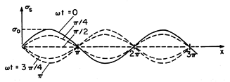
o, which determines the temporal phase and magnitude of the charge density at any given location x, is given. Figure 12.6.2 shows this function represented in space and time. The charge density is always zero at the locations kx x = n
, where n is any integer, and oscillates between positive and negative peak amplitudes at locations in between. When it is positive in one half-period between nulls, it is negative in the adjacent half-periods. It has the x dependence of a standing wave.
Figure 12.6.2 Standing wave of surface charge density. The current density that is consistent with the surface charge density of (18) follows from (3).
With the surface current density in the z direction zero, the fields excited by these surface sources above and below the sheet are TM. The continuity conditions, (12.1.14)-(12.1.17), relate the fields to the given surface source distributions.
We start with Ampère's continuity condition, the x component of (12.1.15)
because it determines the x dependence of Hz as cos kx x. Of the possible combinations of solutions given by (15), we let
The upper solution pertains to the upper region. Note that we select a y dependence that represents either a wave propagating in the +y direction (for
2
> 0) or a field that decays in that direction (for
2
< 0). The lower solution, which applies in the lower region, either propagates in the -y direction or decays in that direction. One of two conditions on the coefficients in (21) it follows from substitution of these equations into Ampère's continuity condition, (20).
A second condition follows from Faraday's continuity condition, (12.1.16), which requires that the tangential electric field be continuous.
Substitution of the solutions, (21), into (6) gives
xa and
xb, from which follows
Combining (2) and (3) we find
The remaining continuity conditions are now automatically satisfied. There is no normal flux density, so the flux continuity condition of (12.1.17) is automatically satisfied. But even if there were a y component of H, continuity of tangential E as expressed by (23) would guarantee that this condition is satisfied.
In summary, the coefficients given by (25) can be used in (21), and those expressions introduced into (6) and (7), to determine the fields as
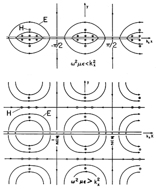
These fields are pictured in Fig. 12.6.3 for the case where
o is real. In the first field distribution, the frequency is low enough so that
2
< kx2. Thus,
as given by (13) has a negative imaginary value. The electric field pattern is shown when t = 0. At this instant, H = 0. When
t =
/2, H is as shown while E = 0. The E and H are 90 degrees out of temporal phase. The fields decay in the y direction, much as they would for a spatially periodic surface charge distribution in the EQS limit. Because they decay in the
y directions for reasons that do not involve dissipation, these fields are sometimes called evanescent waves. The decay has its origins in the nature of quasistatic fields, shaped as they are by Laplace's equation. Indeed, with
2

kx2, E = -
, and we are dealing with scalar solutions
to Laplace's equation. The field pattern corresponds to that of Example 5.6.2. As the frequency is raised, the rate of decay in the y direction decreases. The rate of decay, |
|, reaches zero as the frequency reaches
= kx/
= kx c. The physical significance of this condition is seen by recognizing that kx = 2
/
x, where
x is the wavelength in the x direction of the imposed surface charge density, and that
= 2
/T where T is the temporal period of the excitation. Thus, as the frequency is raised to the point where the fields no longer decay in the
y directions, the period T has become T =
x/c, and so has become as short as the time required for an electromagnetic wave to propagate the wavelength
x.
Figure 12.6.3 TM waves due to standing wave of sources in y = 0 plane. The second distribution of Fig. 12.6.3 illustrates what happens to the fields as the frequency is raised beyond the cutoff frequency, when
2
> kx2. In this case, both E and H are shown in Fig. 12.6.3 when t = 0. Fields above and below the sheet propagate in the
y directions, respectively. As time progresses, the evolution of the fields in the respective regions can be pictured as a translation of these distributions in the
y directions with the phase velocities
/ky.
Transverse Electric (TE) Fields
Consider the case of a z-directed surface current density K = kz iz. Then, the surface charge density
s is zero. It follows from the superposition integral for
, (12.3.1), that
= 0 and from the superposition integral for A, (12.3.2), that A = Az iz. Equation (12.1.3) then shows that E is in the z direction, E = Ez iz. The electric field is transverse to the x and y axes, while the magnetic field lines are in x - y planes. These are the field directions summarized in the second part of Fig. 12.6.1.
In the sinusoidal steady state, it is convenient to use Ez as the function from which all other quantities can be derived, for it follows from Faraday's law that the two components of H can be written in terms of Ez.
In the free space regions to either side of the sheet, each of the Cartesian components of E and H satisfies the wave equation. We have already seen this for H. To obtain an expression playing a similar role for E, we could again return to the wave equations for A and
. A more direct derivation begins by taking the curl of Faraday's law.
On the left, a vector identity has been used, while on the right the order of taking the time derivative and the curl has been reversed. Now, if we substitute for the divergence on the left using Gauss' law, and for the curl on the right using Ampère's law, it follows that
In the free space regions, the driving terms on the right are absent. In the case of transverse electric fields,
z is the only field component. From (32), an assumed time dependence of the form E = Re [
z iz exp (j
t)] leads to the Helmholtz equation for
z
In retrospect, we see that the TE field relations are obtained from those for the TM fields by replacing H
- E, E
H,


and


. This could have been expected, because in the free space regions to either side of the source sheet, Maxwell's equations are replicated by such an exchange of variables. The discussion of product solutions to the Helmholtz equation, given following (9), is equally applicable here.
Example 12.6.2. Traveling-Wave TE Fields
This example has two objectives. One is to illustrate the TE fields, while the other is to provide further insights into the nature of electrodynamic fields that are periodic in time and in one space dimension. In Example 12.6.1, these fields were induced by a standing wave of surface sources. Here the source takes the form of a wave traveling in the x direction.
Again, the frequency of the source current,
, and its spatial dependence, exp (-jkx x), are prescribed. The traveling-wave x, t dependence of the source suggests that solutions take the form of (17).
Faraday's continuity condition, (12.1.16), requires that
and this provides the first of two conditions on the coefficients in (35).
Ampère's continuity condition, (12.1.15), further requires that
With Hx found by substituting (35) into (29), this condition shows that
With the substitution of these coefficients into (35), we have
Provided that
is as defined by (13), these relations are valid regardless of the frequency. However, to emphasize the effect on the field when the frequency is such that
2
< kx2, these expressions are written for that case as
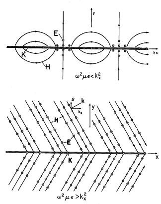
The space time dependence of Ez, and H as found by using (40) to evaluate (29) and (30), is illustrated in Fig. 12.6.4. For
2
> kx2, the response to the traveling wave of surface current is waves with lines of constant amplitude given by
Figure 12.6.4 TE fields induced by traveling-wave source in the y = 0 plane. Thus, points of constant phase are lines of slope
kx/ky. The velocity of these lines in the x direction,
/kx, is called the phase velocity of the wave in the x direction. The respective waves also have phase velocities in the
y directions, in this case

/ky. The response to the traveling-current sheet in this high-frequency regime is a pair of uniform plane waves. Their direction of propagation is along the gradient of (42), and it is sometimes convenient to describe such plane waves by a vector wave number k having the direction of propagation of the planes of constant phase. The waves in the half-plane Y > 0 possess the k vector
At frequencies low enough so that
2
< kx2, points of constant phase lie on lines perpendicular to the x axis. At a given location along the x axis, the fields vary in synchronism but decay in the
y directions. In the limit when
2

kx2 (or f
c/
x, where

2
f), the H fields given by (29) and (30) become the MQS fields of a spatially periodic current sheet that happens to be traveling in the x direction. These "waves" are similar to those predicted by Laplace's equation except that for a given wavelength 2
/kx in the x direction, they reach out further in the y direction. (A standing-wave version of this MQS field is exemplified by Prob. 8.6.9.) In recognition of the decay in the y direction, they are sometimes called nonuniform plane waves or evanescent waves. Note that the frequency demarcating propagation in the
y directions from evanescence or decay in the
y directions is f = c/
x or the frequency at which the spatial period of the imposed current sheet is equal to one wavelength for a plane wave propagating in free space.


