
12.7
Electrodynamic Fields in the Presence of PerfectConductors
The superposition integral approach is directly applicable to the determination of electrodynamic fields from sources specified throughout all space. In the presence of materials, sources are induced as well as imposed. These sources cannot be specified in advance. For example, if a perfect conductor is introduced, surface currents and charges are induced on its surface in just such a way as to insure that there is neither a tangential electric field at its surface nor a magnetic flux density normal to its surface.
We have already seen how the superposition integral approach can be used to find the fields in the vicinity of perfect conductors, for EQS systems in Chap. 4 and for MQS systems in Chap. 8. Fictitious sources are located in regions outside that of interest so that they add to those from the actual sources in such a way as to satisfy the boundary conditions. The approach is usually used to provide simple analytical descriptions of fields, in which case its application is a bit of an art- but it can also be the basis for practical numerical analyses involving complex systems.
We begin with a reminder of the boundary conditions that represent the influence of the sources induced on the surface of a perfect conductor. Such a conductor is defined as one in which E
0 because


. Because the tangential electric field must be continuous across the boundary, it follows from Faraday's continuity condition that just outside the surface of the perfect conductor (having the unit normal n)
In Sec. 8.4, and again in Sec. 12.1, it was argued that (1) implies that the normal magnetic flux density just outside a perfectly conducting surface must be constant.
The physical origins and limitations of this boundary condition were one of the subjects of Chap. 10.
Method of Images
The symmetry considerations used to satisfy boundary conditions in Secs. 4.7 and 8.6 on certain planes of symmetry are equally applicable here, even though the fields now suffer time delays under transient conditions and phase delays in the sinusoidal steady state. We shall illustrate the method of images for an incremental dipole. It follows by superposition that the same method can be used with arbitrary source distributions.
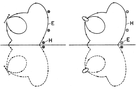
Suppose that we wished to determine the fields associated with an electric dipole over a perfectly conducting ground plane. This dipole is the upper one of the two shown in Fig. 12.7.1. The associated electric and magnetic fields were determined in Sec. 12.2, and will be called Ep and Hp, respectively. To satisfy the condition that there be no tangential electric field on the perfectly conducting plane, that plane is made one of symmetry in an equivalent configuration in which a second "image" dipole is mounted, having a direction and intensity such that at any instant, its charges are the negatives of those of the first dipole. That is, the + charge of the upper dipole is imaged by a negative charge of equal magnitude with the plane of symmetry perpendicular to and bisecting a line joining the two. The second dipole has been arranged so that at each instant in time, it produces a tangential E = Eh that just cancels that of the first at each location on the symmetry plane. With
we have made E satisfy (1) and hence (2) on the ground plane.
There are two ways of conceptualizing the "method of images." The one given here is consistent with the superposition integral point of view that is the theme of this chapter. The second takes the boundary value point of view of the next chapter. These alternative points of view are familiar from Chaps. 4 and 5 for EQS systems and from the first and second halves of Chap. 8 for MQS systems. From the boundary value point of view, in the upper half-space, Ep and Hp are particular solutions, satisfying the inhomogeneous wave equation everywhere in the volume of interest. In this region, the fields Eh and Hh due to the image dipole are then solutions to the homogeneous wave equation. Physically, they represent fields induced by sources on the perfectly conducting boundary.
To emphasize that the symmetry arguments apply regardless of the temporal details of the excitations, the fields shown in Fig. 12.7.1 are those of the electric dipole during the turn-on transient discussed in Example 12.2.1. At an arbitrary point on the ground plane, the "real" dipole produces fields that are not necessarily in the plane of the paper or perpendicular to it. Yet symmetry requires that the tangential E due to the sum of the fields is zero on the ground plane, and Faraday's law requires that the normal H is zero as well.
Figure 12.7.1 Dipoles over a ground plane together with their images: (a) electric dipole; and (b) magnetic dipole. In the case of the magnetic dipole over a ground plane shown in Fig. 12.7.1b, finding the image dipole is easiest by nulling the magnetic flux density normal to the ground plane, rather than the electric field tangential to the ground plane. The fields shown are the dual [(12.2.33)-(12.2.34)] of those for the electric dipole turn-on transient of Example 12.2.1. If we visualize the dipole as due to magnetic charge, the image charge is now of the same sign, rather than opposite sign, as the source.
Image methods are commonly used in extending the superposition integral techniques to antenna field patterns in order to treat the effects of a ground plane and of reflectors.
Example 12.7.1. Ground Planes and Reflectors
Quarter-Wave Antenna above a Ground Plane
The center-fed wire antenna of Example 12.4.1, shown in Fig. 12.7.2a, has a plane of symmetry,=
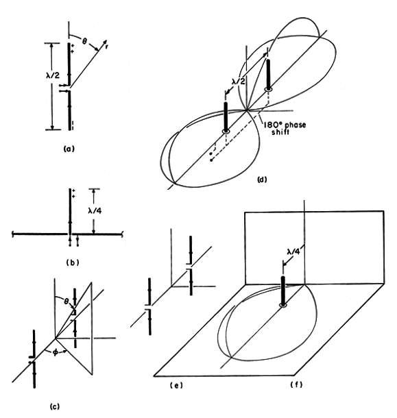
/2, on which there is no tangential electric field. Thus, provided the terminal current remains the same, the field in the upper half-space remains unaltered if a perfectly conducting ground plane is placed in this plane. The radiation electric field is therefore given by (12.4.2), (12.4.5), and (12.4.8). Note that the lower half of the wire antenna serves as an image for the top half. Whether used for AM broadcasting or as a microwave mobile antenna (on the roof of an automobile), the height is usually a quarter-wavelength. In this case, kl =
, and these relations give
where the radiation intensity pattern is
Figure 12.7.2 Equivalent image systems for three physical systems. Although the radiation pattern for the quarter-wave ground plane is the same as that for the half-wave center-fed wire antenna, the radiation resistance is half as much. This follows from the fact that the surface of integration in (12.5.9) is now a hemisphere rather than a sphere.
The integral can be converted to a sine integral, which is tabulated.
9 It is perhaps easiest to carry out the integral numerically, as can be done with a programmable calculator. Note that the integrand is zero at= 0. In free space, this radiation resistance is 37
.
Two-Element Array over Ground Plane
The radiation pattern from an array of elements vertical to a ground plane can be deduced using the same image arguments. The pair of center-fed half-wave elements shown in Fig. 12.7.2c have lower elements that serve as images for the quarter-wave vertical elements over a ground plane shown in Fig. 12.7.2d.If we consider elements with a half-wave spacing that are driven 180 degrees out of phase, the array factor is given by (12.4.15) with ka =
and
1 -
o =
. Thus, with
o from (5), the electric radiation field is
where
The radiation pattern is proportional to the square of this function and is sketched in Fig. 12.7.2d. The field initiated by one element arrives in the far field at
= 0 and
=
with a phase that reinforces that from the second element. The fields produced from the elements arrive out of phase in the "broadside" directions, and so the pattern nulls in those directions (
=

/2).
Phased arrays of two or more verticals are often used by AM stations to provide directed broadcasting, with the ground plane preferably wet land, often with buried "radial" conductors to make the ground plane more nearly like a perfect conductor.
Ground-Plane with Reflector
The radiation pattern for the pair of vertical elements has no electric field tangential to a vertical plane located midway between the elements. Thus, the effect of one of the elements is equivalent to that of a reflector having a distance of a quarter-wavelength from the vertical element. This is the configuration shown in Fig. 12.7.2f.The radiation resistance of the vertical quarter wave element with a reflector follows from (12.5.9), evaluated using (7). Now the integration is over the quarter-sphere which, together with the ground plane and the reflector plane, encloses the element at a radius of many wavelengths.
Demonstration 12.7.1. Ground-Planes, Phased Arrays, and Reflectors
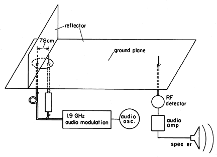
The experiment shown in Fig. 12.7.3 demonstrates the effect of the phase shift on the radiation pattern of the array considered in Example 12.7.1. The spacing and length of the vertical elements are 7.9 cm and 3.9 cm, respectively, which corresponds to
/2 and
/4 respectively at a frequency of 1.9 GHz. The ground plane consists of an aluminum sheet, with the array mounted on a section of the sheet that can be rotated. Thus, the radiation pattern in the plane
=
/2 can be measured by rotating the array, keeping the receiving antenna, which is many wavelengths away, fixed.
An audible tone can be used to indicate the amplitude of the received signal. To this end, the 1.9 GHz source is modulated at the desired audio frequency and detected at the receiver, amplified, and made audible through a loud speaker.
The 180 degree phase shift between the drives for the two driven elements is obtained by inserting a "line stretcher" in series with the coaxial line feeding one of the elements. By effectively lengthening the transmission line, the delay in the transmission line wave results in the desired phase delay. (Chapter 14 is devoted to the dynamics of signals propagating on such transmission lines.) The desired 180 degree phase shift is produced by rotating the array to a broadside position (the elements equidistant from the receiving antenna) and tuning the line stretcher so that the signals are nulled. With a further 90 degree rotation so that the elements are in the end-fire array position (in line with the receiving antenna), the detected signal should peak.
One vertical element can be regarded as the image for the other in a physical situation in which one element is backed at a quarter-wavelength by a reflector. This quarter-wave ground plane with a reflector is demonstrated by introducing a sheet of aluminum halfway between the original elements, as shown in Fig. 12.7.3. With the introduction of the sheet, the "image" element is shielded from the receiving antenna. Nevertheless, the detected signal should be essentially unaltered.
Figure 12.7.3 Demonstration of phase shift on radiation pattern. The experiment suggests many other interesting and practical configurations. For example, if the line stretcher is used to null the signal with the elements in end-fire array position, the elements are presumably driven in phase. Then, the signal should peak if the array is rotated 90 degrees so that it is broadside to the receiver.
Boundaries at the Nodes of Standing Waves
The TM fields found in Example 12.6.1 were those produced by
a surface charge density taking the form of a standing wave in the y
= 0 plane. Examination of the analytical expressions for E,
(12.6.27)-(12.6.28), and of their graphical portrayal, Fig. 12.6.3,
shows that at every instant in time, E was normal to the planes
where kx x = n (n any integer), whether the waves were
evanescent or propagating in the
  y directions. That is, the fields
have nodal planes (of no tangential E) parallel to the y - z
plane. These fields would therefore remain unaltered by the
introduction of thin, perfectly conducting sheets in these planes.
Example 12.7.2. TM Fields between Parallel Perfect Conductors
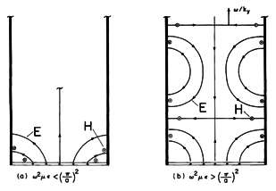
To be specific, suppose that the fields found in Example 12.6.1 are to "fit" within a region bounded by perfectly conducting surfaces in the planes x = 0 and x = a. The configuration is shown in Fig. 12.7.4. We adjust kx so that
where n indicates the number of half-wavelengths in the x direction of the fields shown in Fig. 12.6.3 that have been made to fit between the perfect conductors. To make the fields satisfy the wave equation, ky must be given by (12.6.14) and (12.6.13). Thus, from this expression and (10), we see that for the n-th mode of the TM fields between the plates, the wave number in the y direction is related to the frequency by
Figure 12.7.4 The n = 1 TM fields between parallel plates (a) evanescent in y direction and (b) propagating in y direction. We shall encounter these modes and this dispersion equation again in Chap. 13, where waves propagating between parallel plates will be considered from the boundary value point of view. There we shall superimpose these modes and, if need be, comparable TM field modes, to satisfy arbitrary source conditions in the plane y = 0. The sources in the plane y = 0 will then represent an antenna driving a parallel plate waveguide.
The standing-wave fields of Example 12.6.1 are the superposition of two traveling waves that exactly cancel at the nodal planes to form the standing wave in the x direction. To see this, observe that a standing wave, such as that for the surface charge distribution given by (12.6.18), can be written as the sum of two traveling waves.
10 sin u = (exp(ju) - exp (-ju))/2j
By superposition, the field responses therefore must take this same form. For example, Ey as given by (12.6.28) can be written as
where the upper and lower signs again refer to the regions above and below the sheet of charge density. The first term represents the response to the component of the surface current density that travels to the right while the second is the response from the component traveling to the left. The planes of constant phase for the component waves traveling to the right, as well as their respective directions of propagation, are as for the TE fields of Fig. 12.6.4. Because the traveling wave components of the standing wave have phases that advance in the y direction with the same velocity, have the same wavelength in the x direction and the same frequency, their electric fields in the y-direction exactly cancel in the planes x = 0 and x = a at each instant in time. With this recognition, we may construct TE modes of the parallel plate conductor structure of Fig. 12.7.4 by superposition of two countertraveling waves, one of which was studied in Example 12.6.2.


