
Note: "introduction" starts here
Section Page
Introduction 2
Objective 2
Background/Motivation 2
Technical Background 3
Technical Approach
Research 7
Arm Design and Construction 8
Foil Design and Construction 9
Instrumentation and Data Analysis 9
Testing 10
Schedule 11
Facilities and Resources 12
Conclusion 12
References and Notes 12
Figure Page
1 Reynolds Number vs. Arm Speed 4
2 CD for cylinder vs. Reynolds Number 5
3a CD vs. Arm Speed 5
3b Drag per Span vs. Arm Speed 5
4 Flow Around Circular Cylinders 7
5 Current Arm Design Concept 8
6 Basic Foil Concept (Cross-Section) 9
7 Test Matrix 10
8 Project Schedule Spring 1994 11
9 Project Schedule Fall 1994 11
When astronauts train for their work in space more often than not they do this
underwater in huge neutral-buoyancy tanks. This method offers the advantages of
microgravity simulation and full-scale mockups. However, there is one glaring
difference between the underwater environment and the space environment. This
difference is the viscous drag associated with movement underwater. This
project will model human arm motion underwater using a submerged robotic arm in
an attempt to determine if this drag can be significantly reduced, and
therefore the overall success of the simulation improved.
The techniques to reduce the drag that will be investigated are foils that are
free to rotate around the arm segment and low-drag coatings that will be placed
on the arm and foils. Through measuring the effort required to move the arm
through the water in different configurations of coatings and foils, the effect
of each will be determined, and recommendations as to the feasibility of
improving underwater space simulation will be made.
The objective of this project is to determine whether or not it is possible to
make the underwater training environment currently used by astronauts into a
more accurate representation of the actual space environment. Specifically, the
effects of adding freely-rotating foils (FRF) to a robotic model of the human
arm will be investigated. These foils will be free to rotate around the axis of
the arm, orienting themselves towards the oncoming flow. The foils will act to
streamline the flow around the arm, thereby reducing the drag. In addition, the
effects of applying low-drag coatings (LDC) to both the arm and the foils will
be considered.
For years, NASA has conducted training sessions underwater in neutral-buoyancy
tanks to simulate the weightless environment astronauts experience during
Extra-Vehicular Activity (EVA). Training underwater provides several
advantages, the most frequently cited of which is the ability to provide a
full-scale micro-gravity environment for long time periods. However, water is
fundamentally unlike space in that is has both mass and viscosity. These both
lead to significant drag forces which the astronauts experience. Because they
do not experience any significant drag forces (besides molecular) during EVA,
this leads to an inaccuracy in the simulation. For instance, when an astronaut
attaches something to a satellite mock-up while underwater, there is often
enough drag to prevent the satellite from moving away. The momentum transferred
from the astronaut is transmitted through the satellite to the water. On the
other hand, while in the vacuum of space, there is nothing to receive the
momentum of the satellite, and it will in fact begin to move. Thus the
simulation cannot predict the actual events completely. One proposed solution
is to scale models used in the neutral buoyancy tanks both in size and in
weight, so that the work required to move them is consistent in the two
environments.[1] However, this negates one
of the primary advantages of neutral-buoyancy simulation: the ability to have
full-scale mock-ups. Thus it is desirable to decrease the drag experienced by
astronauts as much as is possible without sacrificing the other benefits of
neutral-buoyancy simulation.
Note: end of "introduction"; "body" starts here
When considering any kind of fluid mechanics problems, such as the drag on an
astronaut's arm, it is very important to identify the regime that is being
considered. This is usually quantified using the Reynolds number
 (1)
(1)
where U is the velocity of the fluid, L some characteristic
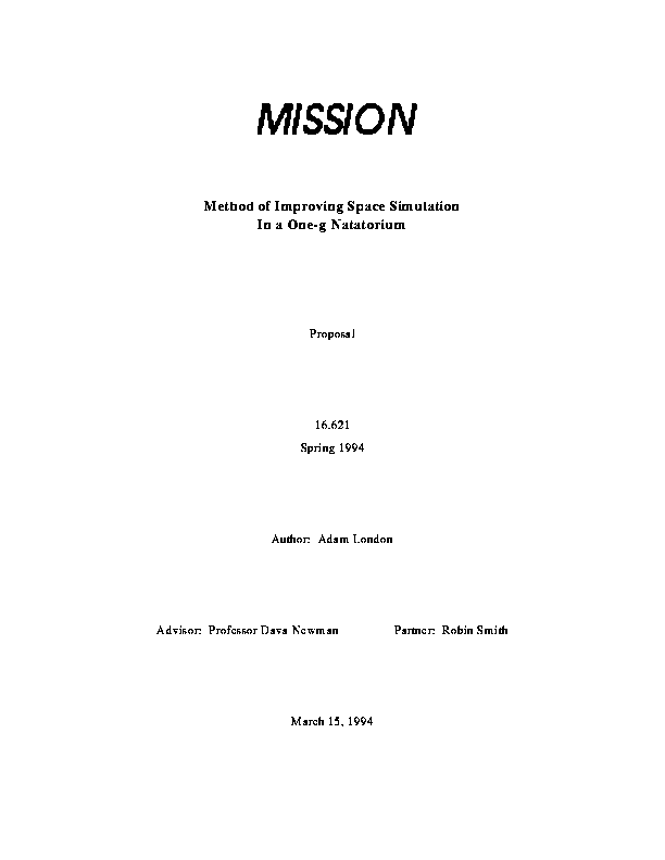
length, and v the kinematic viscosity of the fluid. Figure 1 shows
the Reynolds Number versus arm speed for three different arm diameters.
Thus it is clear that this project will operate under conditions where the
Reynolds Number is between 10 and 200, since human arm speeds are approximately
between zero and four ft/sec. This regime of Reynolds Number is a part of fluid
mechanics where very little research or experimentation is done. Traditionally,
research efforts have concentrated on very-low Reynolds number applications,
usually in the range of zero to approximately twenty; low Reynolds Number
applications, such as boats, sails, and underwater cables, with Reynolds
numbers on the order of 10^4 and 10^5; and high Reynolds
Number applications, such as airplanes, with Reynolds numbers of the order of
10^6 and above. The region where this project resides is basically
omitted because there are very few real applications.
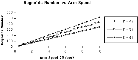 Figure 1 -- Reynolds Number vs. Arm Speed
Luckily, one of the exceptions to this lack of research is in the study
of drag on circular cylinders. In general, drag on a body is due to a
combination of skin friction forces and pressure forces. In an ideal fluid
with no skin friction, by D'Alembert's Paradox, there would be no drag, since
the flow would remain laminar and attached to the body along the entire
contour, and the pressure forces would exactly balance each other out.[2] However, in reality, a fluid must have a
velocity of zero at the surface of any solid, and so a boundary layer is
created.[3] This boundary layer serves as a
transition between zero velocity at the solid and free-stream velocity some
small distance away from the solid. If this boundary layer was to remain
attached to the cylinder through the whole contour, then again, there would be
no drag due to pressure forces, and the only drag would be the relatively small
skin-friction drag. However, this is almost never the case. When the boundary
layer separates from the body, a large region of low pressure appears on the
trailing edge of the cylinder, which can no longer balance the increase of
pressure on the leading edge, so a net drag is produced.[4]
There is no exact analytical solution to the Navier-Stokes equation, which
governs incompressible viscous flow, for the case of a cylindrical section.[5] However, many experiments have been
performed, and the coefficient of drag
 (2)
(2)
which is a pure function of Reynolds number and for incompressible flows is
well tabulated. A plot of it is reproduced in Figure 2. For the regions that
the experiment will operate in (10<=Re <=1000) CD is quite
linear in the log-log plot which corresponds to an approximation of[6]
 (3)
(3)
Using this approximation, we can plot CD and Drag as a function of arm
speed (Figure 3a and 3b)
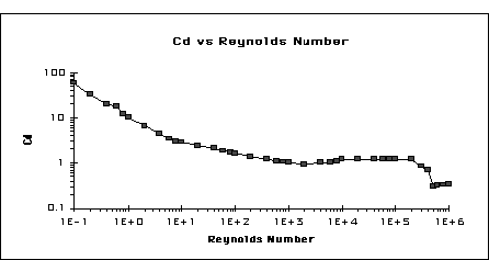 Figure 2 -- CD for a cylinder vs. Reynolds Number
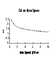
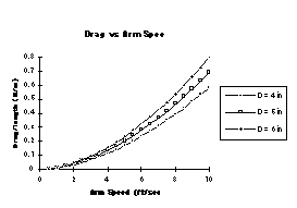 Figure 3a -- CD vs. Arm Speed Figure 3b -- Drag per span vs. Arm Speed
The reason for the extremely high CD is the early separation of
the boundary layer. In order to decrease the drag, it is necessary to keep the
flow attached as long as possible. This is the purpose of an airfoil. It allows
the flow to remain attached almost all the way to the trailing edge. This is
not a fail-proof solution by any means. In the limiting case of very low
Reynolds number, an airfoil will actually have more drag than a cylinder,
because skin friction dominates, and the wetted area (total exposed surface
area) is greater, thereby producing more drag. Also, if the airfoil is
excessively thick, then the flow will still separate before the trailing edge,
causing similar problems. This project is right on the border of both of these
problems, as the Reynolds Numbers involved are fairly low. Moreover, the length
that the foils can be is constrained in that the "person" wearing them must be
able to still move, thereby making them relatively thick. Thus, a careful
analysis will have to be made in choosing the shape of the foils. Most likely,
it will involve a numerical technique to predict the location of boundary layer
separation.
It is also worth noting the sudden drop in CD at
 .
This corresponds to the transition from a laminar boundary layer to a turbulent
one.[7][8] Though it is customary
to associate turbulence with high drag, in this case it actually helps the
situation, because turbulent boundary layers tend to separate later in the flow
than laminar ones. Therefore the counter-intuitive method of making a surface
rougher will actually decrease drag for some situations by forcing the laminar
to turbulent transition to occur at lower Reynolds Numbers. However, it is very
difficult (if not impossible) to conceive that such a transition could be made
to occur in the regime of Reynolds Numbers that this project focuses on.
.
This corresponds to the transition from a laminar boundary layer to a turbulent
one.[7][8] Though it is customary
to associate turbulence with high drag, in this case it actually helps the
situation, because turbulent boundary layers tend to separate later in the flow
than laminar ones. Therefore the counter-intuitive method of making a surface
rougher will actually decrease drag for some situations by forcing the laminar
to turbulent transition to occur at lower Reynolds Numbers. However, it is very
difficult (if not impossible) to conceive that such a transition could be made
to occur in the regime of Reynolds Numbers that this project focuses on.
Finally, the concept of vortex shedding must be addressed. As was stated
earlier, for extremely low Reynolds Numbers,
 the flow around a cylinder is laminar, and skin friction is the only source of
drag. As the Reynolds Number increases, separation begins, and the pressure
forces become increasingly important. Up to
the flow around a cylinder is laminar, and skin friction is the only source of
drag. As the Reynolds Number increases, separation begins, and the pressure
forces become increasingly important. Up to
 ,
the overall flow is basically laminar, and a pair of stable vortices form
symmetrically off the trailing edge. (Figure 4a) However, at
,
the overall flow is basically laminar, and a pair of stable vortices form
symmetrically off the trailing edge. (Figure 4a) However, at
 ,
the two vortices begin to form alternately in time, one above the centerline
and then one below. (Figure 4b) This, known as a Von Karman Vortex Sheet,[9][10] leaves a large wake of
alternating votrices behind it and adds significantly to the drag. An
additional method of overcoming some drag is to attempt to prevent the
beginning the vortex shedding, by placing either some ribbons or a fixed flat
plate called a Splitter Plate along the centerline facing away from the flow
(Figures 4c and 4d).
,
the two vortices begin to form alternately in time, one above the centerline
and then one below. (Figure 4b) This, known as a Von Karman Vortex Sheet,[9][10] leaves a large wake of
alternating votrices behind it and adds significantly to the drag. An
additional method of overcoming some drag is to attempt to prevent the
beginning the vortex shedding, by placing either some ribbons or a fixed flat
plate called a Splitter Plate along the centerline facing away from the flow
(Figures 4c and 4d).
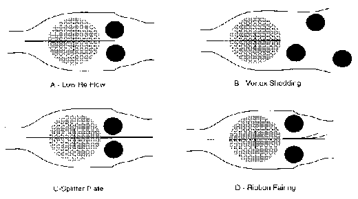 Figure 4 -- Flow around circular cylinders (gray).
Dark circles represent vortices[11]
The project began with background research into past efforts attempting to
minimize the differences between the space environment and the underwater
environment. Also general drag reduction techniques were (and are being)
investigated. Interesting ideas that had not been previously considered include
the Splitter Plate and Ribbons shown in Figure 4, and the use of additives such
as high molecular weight polymers in the fluid itself.[12] In addition, members of Ocean Engineering
department have been consulted, as well as the staff and some members of the
MIT Nautical Association, as to possible low-drag coatings that could be
applied to the arm and foils. Generally the consensus is that the best coating
for reducing drag is one that is minutely ribbed, so as to keep the boundary
layer as small and as thin as possible. In addition, sanding and waxing
techniques have been discussed. Most recently, research has been done in order
to attempt to predict the behavior of the flow when the foils are added. This
has turned out to be much more difficult than originally expected, and will
most likely require some numerical analysis. The results of this will help
determine the shape of the foils that will eventually be constructed.
Research as to possible arm designs has begun. The original concept consisted
of an vertical cylindrical segment that was able to translate vertically and
rotate around its center, to the end of which a two-segment arm was to be
attached. Both of these joints would have been able to rotate freely, adding
two more degrees of freedom to the system, for a total of four. Based on input
during the oral proposal, the decision has been made to limit the lower section
to one segment. This will greatly simplify the design and construction. The
current design concept is pictured in figure 5.
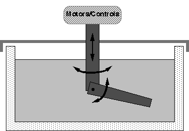 Figure 5 -- Current Arm Design Concept
The motors and controls will be placed above the main column, so as to
remain out of the water. This will greatly reduce the complexity of the
water-proofing process. The joint will as frictionless as possible, so as to
allow the lower segment (representing the arm) to "float" once it is made
neutrally-buoyant. It is currently envisioned that the lower segment will be
constructed out of plastic tubing. A possible candidate is ABS pipe often used
in drainage and sewer applications. Both ends will be capped, and enough
buoyant material, such as Styrofoam, will be inserted to make the segment
neutrally-buoyant in water. The actual join will most likely be open to the
water, as the water should help in alleviating some of the friction. The
biggest concern at the moment is the actual design of the joint and actuator
system. It is not that difficult to design a almost-frictionless joint;
however, making the connection to the actuator frictionless as well will be
very difficult. Designing the joint and the control system will be the primary
focus of the arm design for the remainder of the term.
It was originally believed that foil design and construction would simply
involve looking up drag coefficients for various standard foil shapes, and
using this information to choose a small number of foils to construct. However,
because of the seeming uniqueness of the problem the project addresses, such
information has not been readily available. Airfoils that have the thickness
ratio[13] of 25% to 40% as envisioned are
rarely, if ever used. It is possible that the lack of data stems from the fact
that most research has concentrated on airfoil handbooks, but even references
that discuss foils used on yachts rarely mention foils with thickness ratios
larger than 12% to 15%. In addition, even if such data was available, it is
more than likely that it would not be catalogued for Reynolds Numbers as low as
the ones that would be encountered during tests. For these reasons, much more
investigation must be done, and as was mentioned earlier, it is more than
likely that numerical methods will be used eventually. In addition, other
foil-like techniques, such as ribbon fairings and splitting plates will be
considered, especially if preliminary results show that drag would not be
significantly reduced using a more standard, airfoil-like shape. The basic
concept of the foil as mounted on the arm is illustrated in Figure 6.
 Figure 6 -- Basic foil concept (cross-section)
The motors will be instrumented to provide measurement of required torques when
a particular motion pattern is prescribed by the control system. From this
information, the forces (drag) can be determined, as the moment arms will all
be known. In addition, as the human arm system is being modeled, equivalent
human workloads will be determined, utilizing a model to be provided by the
project advisor, Professor Dava Newman. A videotape recorder will also be used
to record the arms position as a function of time. This data will be digitized,
and velocities and accelerations will be determined.
Testing will begin out of water when the arm is in its final stages of
construction to verify its functionality. During this time, measurements will
be taken to as to the torques required to move the arm in the air. Though this
will not completely simulate a drag free environment since gravity is still
acting, it should provide a rough base-line drag. For completeness, and to help
determine how important the effect gravity is, the arm will also be tested
out-of-water upside down. Once the out-of-water testing is complete, the tests
will move to the tank in the Ocean Engineering Department. The lower arm
segment will be checked for neutral-buoyancy, and tests will commence. The
first stage of underwater testing will attempt to identify the coating that
best reduces the drag. Between two and four coatings will be applied to the
arm, most likely using pre-made sleeves which will fit over the lower segment.
For each coating, measurements will be taken for a variety of simple motions,
and the most effective coating will then be chosen.
There will be a brief break in testing while this coating is applied to each of
the prospective foils. (Again between two and four) Once this is complete,
testing will resume, and each foil (as well as the arm by itself) will be
subjected to another series of motions. In this case, some of the motions will
attempt to simulate possible EVA tasks. Once again torque and position data
will be taken. When all the data has been collected, the final stage of data
analysis will begin. The test matrix is pictured in Figure 7.
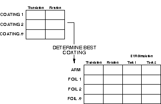 Figure 7 -- Test Matrix
Note: end of "body"; "end" starts here
The schedule for Spring 1994 is pictured in Figure 8 and the schedule for Fall
1994 is shown in Figure 9.
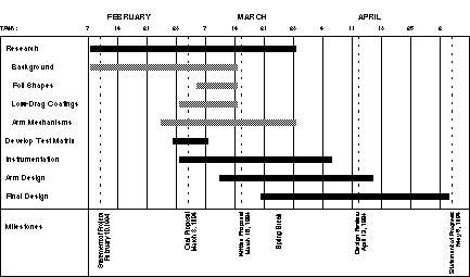 Figure 8 -- Project Schedule Spring 1994
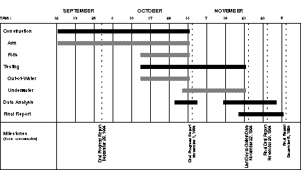 Figure 9 -- Project Schedule Fall 1994
The main facility required is the tank in the Marine Computation and Instrument
Lab, run by the Ocean Engineering Department. Although written permission to
use the lab has not yet been obtained, it should be forthcoming. If the Lab
turns out to be unavailable, the experiment could be conducted in any tank,
including the MIT Natatorium, better known as the Alumni Pool. All other
equipment should be readily available from the department, a local hardware
store, or a marine supply mail order house.
A very approximate and conservative budget is as follows[14]:
	Motors and control systems			$250

	Materials for arm				$100

	Coatings					$100
	Total						$450
The training of astronauts is a very important task, especially as the
publicity and cost of Space Missions continue to rise. Any improvements that
can be made to the underwater simulation environment without sacrificing the
authenticity of the simulation will represent very real developments in the
techniques of space simulation. This project will determine the effectiveness
of two possible methods of drag reduction: freely-rotating foils and low-drag
coatings. In addition, it will provide new experimental data for a regime of
fluid mechanics where very little data has been accumulated.
* See endnotes. <ed.>