Satellites
and antennas
Satellite
Network
Specifications
On
Mars Communication
Radio
Communications
Radio
Specifications
Communication
and Software
Abstract
Digital Signal Processing (DSP) is an important issue in every project involving data transfer and Mission 2004 is no exception. A regular data transmission from Mars to Earth usually includes 20-40% noise, which means that one or two bits out of every five transmitted are lost. As a consequence, about one-third of the data will be unreliable. A more thorough discussion of the problem may be found in Appendix A.
Concerns
For our particular mission, we wanted to choose hardware and an error-control code for all transmitting equipment (e.g. satellites, rovers, LMRs, space suits) with the following characteristics:
- Able to remove up to 50% noise from any transmission;
- Simple enough to run everywhere in real-time, eliminating signal delay;
- Efficient with respect to the computational power used for a single transmission; and
- Reliably effective.
- Single-error-correcting (SEC) Hamming codes,
- Reed-Muller (RM) codes,
- Bose-Chaudhuri-Hocquenghem (BCH) codes, and finally,
- Reed-Solomon (RS) codes.
Mission Integration
After deciding on the error-control code, we turned our attention to its implimentation. Since our mission involves so many different environments that have to run DSP, they were divided into two groups:
- Equipment capable of running DSP software with its own CPU (e.g., satellites, base station, big rovers), and
- Equipment incapable of doing so (e.g., LMRs, space suits) because of limited computational power.
- Getting a digital signal on input,
- Processing it in real time and converting it into analog, and
- Sending the signal to the antenna through the output.
DSP Black Box Specifications (roughly estimated)
Dimensions:
from 7cm x 10cm x 3cm to 15cm x 20cm x 10cm, depending on the power supply
and the data transfer rate supported.
Weight:
from 0.3kg to 5kg, again depending on the power supply and data transfer
rate.
Input:
digital signal from digital cameras, computers, analytic devices through
a serial port (e.g. RS-485, USB, or Firewire), depending on the data transfer
rate. For better understanding -- see Appendix B.
Output:
Analog radio signal to an X-band or Ka-band antenna.
[1] Lee, L., Error-Control Block Codes for Communication Engineers
Appendix A
 |
 |
 |
 |
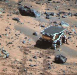
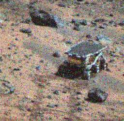
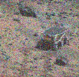
| This series of images illustrates the
need for high-quality noise reduction codes. Each frame is the same photo
of the Mars Pathfinder rover (Sojourner) with different amounts of noise:
0% (upper left), 5% (upper right), 20% (lower left), and 40% (upper right).
Even 5% noise represents significant signal degradation, but typical "uncorrected"
signals from Mars contain upward of 20% noise and 40% noise is sometimes
encountered. With good noise-reduction routines, like Reed-Solomon
codes, we can
"remove" about 50% of the noise from any data transmitted, with an expectation of losing about one bit out of10,000. |
Appendix B
|
|
|
|
|
|
|
RS-485
|
10Mbps
|
32
|
|
|
|
USB
|
40Mbps
|
127
|
|
|
|
Firewire
|
400Mbps
|
64
|
|
|
References
[1] Lee, L., Error-Control Block Codes for Communication Engineers
[2] Co-Optic Inc.,
http://www.co-optic.com/reedsolm.htm
[3] MacInfo, Processor
Power Consumption
[4] Broniatowski, D,
"Sattelites and antennas"
Author: Jordan Brayanov (jordan12@mit.edu)
A printer-friendly version (PDF) could
be found here.