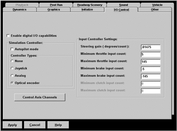
STISIM Drive - I/O Control Tab Box
Your first time into the
configuration menu will display the tabbed box with the I/O Control tab as the
active tab. The actual contents of the box will differ from those shown below, but
the options will be the same. From this tabbed box you will be able to set all
of the parameters that deal with getting the correct input signals into the
simulator.

The first option you see in
the I/O Control tab box allows you to enable and disable the use of the digital
input and output option. During any simulation run you can use the DI, DO, and TDO events to control hardware that is connected to
the simulator computer. This assumes that you have the correct hardware (CIO-DIO24H card) installed in
the simulation computer. A check inside the option box means that the DI, DO
and TDO events will be active if they are included in your current scenario. By
un-checking the option you can deactivate these events without having to remove
them from your scenarios.
In order to traverse the
scenario that you build and specify, you must tell the simulator how this will
be done.You have 2 choices, either the autopilot mode where the program runs
itself, or driving the scenario using the controllers that are hooked up to the
system. Which ever option is used, you choose it by clicking on one of
the options listed in the "Simulation Controller" frame. As you
will find, if you try different options, only one option can be set at a time.
The autopilot mode is handy
because you can run the simulator without any controller hardware connected to
the system. This is ideal for checking scenarios before you actually have
people drive them. When using the autopilot option, the program will
automatically set the speed of the vehicle and its lane position to the values
for Maximum vehicle speed and Lane position specified in the Vehicle and Initialize tab
boxes respectively. As the simulation runs the vehicle will not steer itself
and therefore will remain in the same position in the roadway lane and will run
into anything that is within its path, will not stop at signal lights, will not
stop at stop signs and will collide with other vehicles. While in autopilot
mode you have some control over the vehicle by using the keyboard. Pressing the
U (up or increase) and D (down or decrease) will adjust the speed of the
vehicle while the L (move left) and R (move right) will change the vehicle's
lane position. The speed is changed in 1 foot/second increments while the lane
position is changed in increments of 1 foot. You can also respond to the divided
attention symbols by pressing the 1 key for the horn, the 2 key for the left
turn signal and the 2 key for the right turn signal. A complete list of
keyboard commands that can be used during a simulation run can be found in the
section describing STISIM Drive's Run option. Even
if you have the autopilot mode activated, you can still use the specified
controller for entering divided attention inputs. To do this make sure that one
of the Controller Types is marked.
The Joystick option
requires a 2 axis joystick with at least 2 buttons. We recommend a Thrustmaster
Formula T2 system. This is a system that we have used exclusively in the past
and we can guarantee it will work. Well at least we guarantee it will work
under Windows 95, as for Windows NT all bets are off. If you would like to try
and use a joystick of your own, the X axis (left to right) is the steering axis
and the throttle and brakes are split on the Y axis (forward and back). The
analog option requires an analog to digital input board that is compatible with
a Metrabyte DAS-4 card, and potentiometers for reading the driver's inputs. The
last controller option is for systems with an optical encoder interface board.
This option includes a force feedback steering wheel system that simulates road
feel through the steering wheel. Information on the hardware and installation
of the various controller systems can be found the hardware configuration help section.
Systems using the optical
encoder hardware interface, have an extra advantage over the other systems. The
computer board that interfaces with the optical encoders has an extra channel
on it (if you are not using the advanced dynamics
with a manual transmission). This channel can be used in case one of the other
channels is malfunctioning. However, in order to use the other channel, you
must tell the program which signal is coming through on which channel. To do
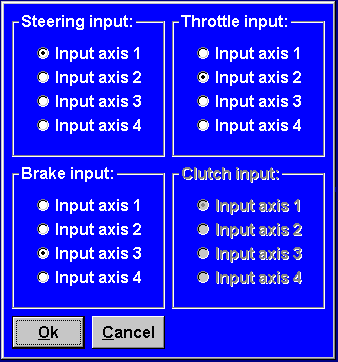
this, you must click on the "Control Axis Channels" button. Clicking
this button will display the following dialog box:

As you can see by looking
at the dialog window, there is an input axis required for each of the possible
control inputs. For each control input that you will be using you will need to
specify which of the optical encoder control axis will be used. Any of the
optical encoder's input axis can be used for any controller. The important
thing is that you assign a separate input axis to each type of control input,
otherwise you will get incorrect results when trying to control the vehicle. To
specify the input axis for a particular controller input, simply click on the
radio button that corresponds to the desired axis. On the main optical encoder
board, the top connector (one closest to the top of the board) is axis 1 and
the bottom connector is axis 2. Axis 3 and 4 are located on a second connector
that is attached to the main board. Axis 3 is the top connector (closest to the
top where you would screw it in) and axis 4 is the lower connector. STISIM
Drive is usually configured so that the steering input is on axis 1, the
throttle is on axis 2, and the brakes or on axis 3. This leaves axis 4 as your
backup channel. Your system does not have to be configured this way, but we
recommend it.
Finally, the simulator
requires some information about the input signals that it will be receiving.
This information is used to convert the input values into variables that the
simulator can understand and use. These parameters are grouped together inside
the "Input control settings" frame. You must set these values before
attempting to use the simulator otherwise when you try to use the pedals or
steering wheel, you may not get any inputs. To help you set these values, we
have included an utility program that can be found in the Tools subdirectory
(C:\STISIM\Tools) named CalPot32.
Looking at the "Input control settings" parameters you will need to specify a steering gain and the minimum and maximum counts for each pedal. You can set all of these parameters with the assistance of CalPot32. Follow the instructions for hardware setup and using CalPot32 before trying to set these values. Once the hardware has been configured use CalPot32 to read the required values. The simplest way to determine the steering gains is to set the steering wheel so that it is at the zero position (the wheel is at zero not necessarily the counts). Now turn the wheel 90 degrees to the left and read the steering wheel count (number displayed to the right of the steering progress bar) and write it down. Now steer the wheel 180 degrees to the right and write that number down. To compute the gain, simply subtract the first number from the second one and then divide 180 by this new number. This will give you the steering gain. Next check to make sure that the steering direction is correct. If you steer the wheel to the right and the numbers increase then the steering gain is positive, if the values decrease, then the gain should be negative. The values for the pedals are much easier to set. The minimum count is the value when you are not touching the pedal and the maximum count is the value when the pedal is fully depressed. Don't worry about direction, STISIM Drive will take care of the direction all by itself. If a value is negative, make sure that you include the negative sign when you enter the values in STISIM Drive. For each pedal we recommend that you trim 5 to 10 percent of the value off so that there is a little deadband at minimum and maximum pedal position. This will help prevent problems if the input signals are noisy or the maximum or minimum values change by a couple of counts each time the pedal is used.