STISIM Drive - Hardware Configuration and Setup
STISIM Drive is a
specialized simulation environment that has been developed over many years and
has been designed to run on Intel Pentium based personal computers. The simulation
has been optimally designed for both speed and cost and therefore it requires
certain hardware in order to operate correctly. Although personal computers are
famous for their open architecture, we cannot be certain that the system will
work with any equipment that is not specified below. The following is a list of
the simulator’s minimum hardware requirements:
- Intel Pentium based computer running at 200 MHz
or faster
- A minimum of 128 megabytes of Random Access
Memory (RAM)
- A hard disk drive with 100 MB of free disk space
- One (1) Parallel printer port
- A graphics card using a 3DFx Voodoo chip set
- A multiple frequency monitor (minimum 17 inch
diagonal)
- A VGA card and VGA monitor for a dual display
system (the VGA monitor for the experimenter's display and the multiple
frequency monitor for the driver's driving scene)
- Either a joystick card, Optical Encoder
Interface card with Optical Encoders and a Digital input/output Interface
card, or an A/D (analog to digital) interface card.
- A SoundBlaster or 100% compatible sound board
- Amplified stereo speakers
- Hardware protection key
As much as we have tried to
make the installation and setup of STISIM Drive as simple and painless as
possible, we may not have totally succeeded. This is mostly due to the ever
changing nature of the computers as well as underlying operating system
problems. It seems that we are capable of installing the software and getting
the systems going, but what happens when the system leaves our caring hands and
is constantly being used by a variety of people? or if the system crashes? or,
heaven forbid, you decide to change or add some hardware to your computer. This
is when things can get a lot tricky and we may not even have an answer.
Therefore, this section is intended to provide some information on the
simulator setup and installation so that you may perform some preliminary
trouble shooting yourself, especially if you will be changing the hardware
configuration or installing everything yourself. It also provides good insight
into the internal workings of STISIM Drive and we recommend that you read
through it even if you are not experiencing any difficulties. Finally, although
we try to provide top notch user support to all of our customers, there can be
occasional delays when responding, and therefore any trouble shooting that you
can perform yourself can help eliminate the problem.
One other important note
that is applicable to systems running under Windows NT. Since STISIM Drive
requires specialized hardware in order to run, you must setup your
system so that STISIM Drive users have Administration privileges, if
not, debugging problems with the system will be impossible. We realize that
this may not be the practice employed by some organizations, but the simulator
is designed to run best when it is not incorporated into an organizational
network (the last thing you want is someone demanding resources from the
simulation computer in the middle of a simulation run), and therefore should
not be added to any existing network. Since this is the case setting up an
account for STISIM Drive users that has Administration privilege should not
cause problems. When we set machines up at STI we always assign the following:
User Name: stisim
Password: STISIM.
For your information the
administrative logon procedure is as follows:
User Name: Administrator
Password:
On systems that utilize
multiple computers, logging in can become tedious especially on the side
display systems or a dynamics machine. In general, when the system boots and
the user logs in, these systems run their respective part of the simulator and
do not require any user interaction (with the exception of the user logging
in). If you would like the user to be able to skip the log in process and have
the machine log them in automatically, we have provided a solution. In the
Tools folder (generally C:\STISIM\Tools), we have provided a registry file
named AutoBoot.Reg. Simply start the Windows Explorer, go to the Tools folder,
and double click on the AutoBoot.Reg file. This will add 3 lines to the system
registry that will then make the system automatically log in the user. Using
this approach, each of the side systems will then boot into the program and the
only interaction that should be necessary is with the center system.
In general, the hardware
configuration and STISIM Drive installation fall into the following categories:
Complete_Installation
Graphics
Sound
Input/Output
Networking
Software Installation/Uninstall
Hardware_Protection_Key
Video
Tools
Obviously, there are numerous other areas about the computer and various hardware and software that can be discussed, but we will only touch on the above areas because they are the only ones that directly affect STISIM Drive. Although it is not mandatory, it is probably best to get the hardware configuration taken care of first before you install the software and try to run the software.
STISIM Drive can be run on several operating systems and can be configured in a number of different ways. Currently, STISIM Drive can run on Microsoft's Windows 95, Windows 98 and Windows NT. We generally recommend that you use Windows NT (with service pack 3) because of its true 32 bit operation, and because it provides the most consistent real-time operation thus allowing constant frame rates to be obtained during simulation runs. The other operating systems also provide this capability but do not seem to be as reliable in terms of frame time operation. However, since Windows NT does not provide a wide range of joystick support, the simplest STISIM Drive configuration (using a ThrustMaster T2 or equivalent joystick) must run under Windows 95 or Windows 98. As for the simulator configuration, most differences occur in the input/output cards than anywhere else. The simulator's input and output can be controlled with a joystick, analog potentiometers, or with an optical encoder setup. In each case a little different setup is required.
The most difficult hardware setup with STISIM Drive involves multiple computer systems that are used for either wide field of view displays, or for our advanced dynamics system. In these cases, a network connection is required so that the various processors can communicate with each other and keep the simulator in sync. The problem with the network communication setup is that it can not be automated and therefore must be done by hand. This is not necessarily a difficult task but can be time consuming especially if the operating system decides not to cooperate.
As was mentioned previously, STISIM Drive comes in a variety of flavors, and each of the different configurations is setup a little different than the others. Each configuration runs the exact same software, it is the hardware configuration and then the software configuration that will be different for each system. Since this is a section on the STISIM Drive hardware, only the hardware configuration will be discussed here. A discussion on the simulation software configuration can be found elsewhere. The following table will let you know the required hardware boards and their locations for each STISIM Drive configuration:
|
STISIM Drive System |
Boards (Bus Type) |
|||
|
Center Computer |
Left Computer |
Right Computer |
Dynamics Computer |
|
|
Single Screen |
VGA card (PCI) |
Not used! |
Not used! |
Not used! |
|
Wide Field of View |
VGA card (PCI) |
VGA card
(PCI) |
VGA card (PCI) |
Not used! |
|
Single Screen |
VGA card (PCI) |
Not used! |
Not used! |
VGA card
(PCI) |
|
Wide Field of View |
VGA card (PCI) |
VGA card
(PCI) |
VGA card
(PCI) |
VGA card
(PCI) |
In the above table, only the
optical encoder interface is mentioned. If you have a system that uses a
joystick then chances are you do not need an additional input card because more
than likely you will be using the game port on the motherboard or sound card.
Therefore you can ignore all references to the Optical encoder and Digital to
analog cards listed. If you have a system that uses an analog interface for the
driver's inputs, then everywhere you see the Optical encoder card listed,
replace it with Analog card and ignore all references to the Digital to analog
card.
One final note before we get into each individual area. The open architecture of the computer system that STISIM Drive operates on, makes it both a very useful tool and a royal pain in the gluteus maximus. Every piece of hardware that is installed in the computer system requires special software drivers and other additional system fine tuning in order for the device to operate correctly. Unfortunately for you, so does STISIM Drive. Because STISIM Drive utilizes existing hardware, you are forced to play the setup game. With this in mind, we highly, very, largely, enormously, extremely, greatly, much, hugely, eminently, exceedingly (sorry that’s all the thesaurus listed) recommend that you set up the system with only the drivers that STISIM Drive requires. Otherwise, if there are conflicts, we won’t be able to help solve the problem because we may not have the same hardware and software drivers as you. Therefore, when going through the remainder of this section, keep in mind that you may want to set up the computer so that it is configured differently for STISIM Drive than for other applications that you have.
If for some reason you are configuring the computer system yourself or had a catastrophe that you are trying to recover from, the following are the basic steps that you will need to follow in order to get STISIM Drive back up and running:
1. If you are recovering
from a disaster and need to re-install Windows, try to save any files or other
work that you currently have stored on your hard disk. In general the
installation should leave your computer pretty much intact, however, "An
ounce of prevention is worth a pound of cure!"
2. Re-install the Windows operating system that you are using. You will need to
follow the installation instructions, and no help will be provided here for the
Windows installation.
3. If you are using a system that includes network communication, have your
network information for the computer on hand (computer name, network name, IP
addresses, etc.). These will be asked for during the installation procedure.
4. After the operating system is installed and the system comes up, check the
network communication if you can. It is best to find out if there is a network
problem earlier than later.
5. Adjust the VGA display screen as you see fit.
6. If you are using Windows NT, install Windows NT service pack 3.
7. Install the sound board drivers and check the sound system to make sure that
it is functioning properly.
8. Install the 3DFx graphics card drivers and check them to make sure that they
are functioning correctly.
9. To be safe, check the network connection again.
10. If you have Microsoft's Internet Explorer 4.0 or higher, reinstall it. This
will allow the on-line help to work correctly.
11. If you are using a Windows NT system, use the User Manager
(Start/Programs/Administrative Tools/User Manager to set up a driving simulator
account. When setting up the account, set the User Name to stisim and the
Password to STISIM. Also assign the account Administrative privileges so that
if you have to fool around with hardware, you can. Finally, set the password so
that it never expires.
12. Log onto the machine as stisim and Install STISIM Drive
13. Put any files that you backed off of the computer in step 1 back onto the
machine.
14. You must now setup the input/output control cards so that STISIM Drive can
recognize the driver's inputs. Review the input/output
section of this document for details on doing this.
This should be all that is necessary (with a lot of rebooting) to get the system up and running for the first time or to get it going again after a complete and total "Blue Screen of Death" system crash.
STISIM Drive requires a
special graphics board in order to use the simulator and it will not run on the
standard VGA cards that are installed in most computer systems. The graphics
cards that STISIM Drive requires must have a 3DFx Voodoo chip set built into
them. As far as we know, any graphics card that has a 3DFx Voodoo chip set and
the proper drivers can be used to run the simulator. As of the writing of this
document there were two flavors of the Voodoo chip set, version 1 and version
2. As time goes on this will undoubtedly change but it is anticipated that the
basic ideas presented here will remain the same. The graphics card that
contains the 3DFx Voodoo chip set can peacefully coexist with your standard VGA
card, this is because the Voodoo card generally does not have a VGA chip set on
it. This means that you can not simply install a Voodoo graphics card and
disregard your VGA card, the system requires both.
If you only have a single monitor and need it for both the roadway display and your Windows display, most of the Voodoo cards come with a pass through cable. This cable allows the output from your VGA card to be passed to the Voodoo card and then the Voodoo card send the correct signal out to the monitor. To setup your system for this type of operation simply use the pass through cable provided with your Voodoo card and plug it in so that the output of the VGA card (15 pin female connector) goes into the input port (15 pin male connector) of the Voodoo card. Next, plug your monitor into the output port (15 pin female connector) of the Voodoo card. When STISIM Drive is run, it will automatically switch between the Windows screen (where all of the setup for the run is performed) and the roadway display scene. At the end of each simulation run, the program will automatically switch you back to the Windows screen. If you have 2 monitors, then the pass through cable is not needed, simple plug each monitor into the desired graphics card and you will be ready to run.
Before attempting to run the simulator, you will need to install the drivers for the 3DFx graphics card. Included with your graphics board should be a disk that contains the necessary drivers. To install the drivers, simply follow the instructions that come with your graphics board. Most of the installation packages come with some sort of demonstration program or applet that allows you to check to see if the installation was successful, we recommend that you first make sure the installation was successful and that you can produce the demonstration graphics before proceeding on to STISIM Drive. In general this will make your life a lot easier. STISIM Drive uses a graphics system that automatically checks for the existence of a Voodoo chip set, if it does not find one, any number of messages may be generated by the system. The most frequent include:
Expected Voodoo driver but
was not found
STIGVS.DLL could not be found
When running STISIM Drive, if either of these messages occur, then the most likely problem is that the Voodoo graphics drivers are not installed.
One other error message that you may encounter when running the simulator is the following:
Error 16: Expression too complex
This is the dreaded "Expression too complex error" and it is caused by a problem with a file called Glide2x.dll. When installing the drivers for your Voodoo card, the installation program installs a file called Glide2x.dll. Some manufacturers create their own custom version of Glide2x and these are not always compatible with STISIM Drive. This problem can be overcome by copying a working version of Glide2x.dll into the STISIM Drive directory. First you will need to know if you are using a Voodoo 1 or a Voodoo 2 graphics board. Next, got to the Tools directory in the STISIM Drive directory (generally it is C:\STISIM\Tools). In the tools directory you should find the following files, Glide2x.voodoo1 and Glide2x.voodoo2. If you have a Voodoo 1 card, simply copy the Glide2x.voodoo1 file into the STISIM Drive directory and rename it Glide2x.dll. If on the other hand you have a Voodoo 2 cards, then copy the Glide2x.voodoo2 file to then STISIM Drive directory and rename it as Glide2x.dll. This should then allow STISIM Drive to function properly. Doing this also allows other programs that require the Voodoo card to use the Glide2x file that came with the card.
Special Installation Note: Some Voodoo2 cards will not work under Windows NT unless it is configured with Service Pack 3, therefore we recommend that if you are configuring a system yourself and you will be using Windows NT, you install Service Pack 3. This should not effect the system and includes newer version of most of the operating system.
The second component of the graphics system is the display that shows the graphics being generated. Large computer monitors, small monitors, overhead projectors, video projectors and television consoles can all be used for displaying the roadway scene. Normally, either a large or small computer monitor is used, however, if a larger display is desired, projection systems can be used to display the roadway scene as large as 100 inches (diagonal). Although to do this you may lose a little video resolution. In general there are 2 different ways to project the roadway images. You can use an active matrix projection display or a video projector and a VGA to NTSC converter box. As you would expect, there are pros and cons to both of these approaches and the approach that you choose depends upon your particular application and resources. The first method works very well and there is no loss of video resolution, however this method tends to be expensive because the higher the resolution the more expensive the display systems are, especially if you want a very bright display. The second method is cheaper, but you lose some video resolution because the NTSC signal has less resolution than a standard VGA signal. This method is the same as using a television console except that instead of using a picture tube, the image is projected onto a screen using a Liquid Crystal Display (LCD) projection. Current projectors are inexpensive and weigh as little as 2 pounds so that they are very portable. As was mentioned, this method does require a converter box that takes the VGA signal from the graphics card and converts it into an NTSC signal that the projector can use. When doing the conversion, some of the original display is lost, therefore the size of the roadway display scene must be adjusted so that the projection display shows the entire scene. STISIM Drive allows you to size the screen so that it is displayed correctly. You do this when you specify the your system's configuration.
For the best results when using the STISIM Drive environment, we recommend that you set your default "Windows" graphics mode to a minimum of 800x600 with small fonts, or 1024x768 with large fonts. This can be done using the display option in Window's control panel. This will produce the best looking as well as the easiest to use display screens.
STISIM Drive can be used with either a single monitor or multiple monitors (roadway display and experimenter's screen). If you are using a system with a single monitor and are using the pass through cable so that the roadway display scene can be displayed on the same monitor as the Windows environment, then you will need to proceed with a little caution. First, you will need to make sure that the system has been connected correctly. With your graphics card you should have received a pass through cable. This cable allows you to connect your VGA card to the roadway display graphics card. Take the cable and plug it into your standard VGA card. The other end should then be connected to the roadway display graphics card. Finally, plug the monitor into the outlet of the roadway display graphics card. The second concern occurs when starting a simulation run. STISIM Drive will perform some initialization in order to set the system up for your simulation run. At some point during the initialization process the monitor will go blank. Don't be alarmed this is standard operating procedure. Wait about 5 seconds for the monitors to warm up then simultaneously press the Alt and F2 keys. This should start the simulator. If it does not, wait another 5 seconds or so and try again. After several tries, if this does not work, then check the troubleshooting section for additional help.
To enhance the driving experience, STISIM Drive uses several feedbacks to the driver, one of which is sound. Sound is used to provide road noise, engine acceleration and deceleration, tire screeches, off road tire sounds, and police sirens (when the driver has done something fundamentally wrong, like running a red light). Because these sounds are played on a board with its own processor, and are played in the background while the simulation runs, they do not adversely effect the frame rate of the simulation. Tire screeching will occur if the vehicle is cornering too fast or braking to hard. Siren sounds occur if the driver runs a red light or if a police officer is present when the driver is speeding (as defined in the event file). Finally, if the driver hits another vehicle, or runs off the road, a crash will occur. This crash includes a cracking windshield and the sound of tires screeching and twisting metal. An additional feature of STISIM Drive's sound system is that it allows you to create and playback your own recordings using the Scenario Definition Language’s PR event.To provide this auditory feedback, sounds are specified and played using WAV files and a personal computer sound card. The sound files are specified using the sound tab option in the configuration menu. Nowadays, most computer systems come equipped with some type of sound card that is capable of playing WAV files, this makes it easy because the drivers are already loaded and the system is ready to go. However, sound cards can fail and if you have to install Windows NT Service Pack 3, your sound drivers may be written over.
If you are installing a sound card of your own, we recommend an ISA bus based card (AWE64) is possible. These cards come with sound memory on the card and when sound files are needed they are loaded into this memory and then played back from it. This means that the sound system does not require system RAM which makes the system run smoother. The gotcha with ISA sound boards is that their installation can be tedious. You will need to use drivers provided by the sound board manufacturer. If you must use a PCI bus sound card, they tend to be a lot easier to install but require some RAM memory in order to run. In any event you will need the card's manufacturer to provide sound drivers and installation instructions for your operating system.
To check whether your sound card has been installed correctly and is currently active, use the Multimedia applet found in the control panel. The simulator also comes with a variety of sound files already available. These files can be found in the Sound directory under the STISIM Drive directory (usually C:\STISIM\Sound). You can specify which recordings will be played with which event using the sound tab in the simulator configuration option. One final note on the use of auditory feedback during a simulation. If you will be creating your own recordings and using the Play Recording (PR) event, you will need to purchase some additional software that allows you to create WAV file recordings. Then you can simply use these WAV file recordings with the PR event to provide your own custom auditory feedback.
Special Note: At the time of this writing, SoundBlaster PCI cards do not work with Windows NT Service Pak 4. Basically this combination completely destroys Windows NT and a complete reinstall is necessary in order to get your computer working again. Therefore, if you are upgrading your hardware or putting a system together yourself, we highly recommend that you do not use Windows NT Service Pak 4 and use Service Pak 3 instead.
One of the most difficult aspects of the driving simulator is installing and then configuring the input/output cards that handle the driver's inputs. There are currently 4 different controller options and one additional output option:
Joysticks
Analog
Active Steering
Manual Transmission
Additional_I/O
In general we do not recommend using a joystick for several reasons, they are slow (in terms of the amount of time it takes to read an input), they generally don't have as much resolution as other input devices and they have reduced face validity. However, joysticks have one huge advantage, they are considerably less expensive then their controller counterparts. Another draw back to most joystick controllers is that they do not have drivers for running on Windows NT, therefore, we recommend that if you are going to be using a joystick configuration for your inputs, you only use it when running under Windows 95 or 98.
In order to use a joystick controller you must first have a game port somewhere on your computer. Virtually every sound card that is available for the PC has a game port included so this is generally not a problem. The game port is a wide 15 pin female port. The next thing you need is a joystick or game port driver. This is generally included with the software for configuring your sound card. You will need to follow the manufacturer's installation instructions for doing this. Once the driver is installed you should use the "Game Controllers" or "Joystick" or "Multimedia" option in Windows Control Panel to configure the joystick and insure that it is operating correctly. After you have confirmed correct operation, you should then run the CalPot32 utility (discussed in the Tools section) so that you can configure the joystick for use with STISIM Drive. When using CalPot32, pay particular attention to the joystick buttons because you will need to know which buttons control the horn input (needed for starting the simulator and the horn divided attention (DA) event), and the left and right turn signal inputs (used for the divided attention (DA) event). When you run the CalPot32 program, the important parts of the display are the axis input values (which are used to specify the steering and pedal gains) and the Main Controller's Port B dialog box. In the Port B box the 3 lights on the left should correspond to the horn, left and right turn signals. Each time one of these is activated, the light should change colors.
For our joystick controllers and the ones that we sell directly to customers, we use a ThrustMaster T2 system. It has pedals and a steering wheel and includes a shifter that is used for the left and right turn signals. It also has 2 red buttons that act as the horn buttons. These units have a good track record and have been very reliable in the past.
An analog to digital controller configuration is very accurate for reproducing actual driving conditions, and requires an analog to digital converter card and potentiometer inputs. The potentiometers are attached to the steering, throttle and brake inputs and then fed to the A/D card, along with switch closure inputs for the divided attention task. Generally, this configuration is used when a vehicle cab is used as the driver station, and the vehicle's steering wheel, accelerator pedal and brake pedal are connected to the input potentiometers, and the horn button and turn signal switches are connected as switch closures. The A/D card that STISIM Drive supports is a ComputerBoards Inc. CIO-DAS08 card or anything that is 100 percent compatible (such as a Metrabyte DAS-4 card).
When you install the CIO-DAS08 card you will need to know the board's address. If you received a complete system from us then the board's address should be set to 320 (hexadecimal). This is important because of the installation procedure. Once the board is installed, you will need to run the ComputerBoards InsCal32 program. This should be found in a subdirectory named CB (C:\CB). When you run the Inscal32 program the first thing you must do is add a card. Simply right click on the button that looks like a computer board and has a big red plus sign in the lower left corner. This icon allows you to add computer boards to your system. When the dialog box appears you will need to scroll through the options until you come to a listing for the CIO-DAS08 card. Click on this card and then choose Ok. In the main Inscal32 program window, the CIO-DAS08 card should now be listed and should have a number associated with it, remember this number it will be important in just a bit. Now that the system knows that there is a card present, you need to configure the card. You do this by clicking on the button with a picture of a computer board and no other symbols. When the dialog window opens, you will need to specify the address for the card. Remember if you received the system from us, our boards are set to a value of 320 (hexadecimal). You can then choose Ok to return to the main Inscal32 window and then exit the program. At this point you will now need to run the CalPot32 program that is included with STISIM Drive. CalPot32 has its own help file to help guide you through the process. The important parts of the CalPot32 display are the axis input values (which are used to specify the steering and pedal gains) and the Main Controller's Port B dialog box. In the Port B box the 3 lights on the left should correspond to the horn, left and right turn signals. Each time one of these is activated, the light should change colors.
Running CalPot32 serves 2 purposes. First it configures the system so that STISIM Drive knows what is going on, and second it allows you to check and see if the STISIM Drive controllers are acting correctly. After starting CalPot32, the first thing you want to do is choose the Analog Controller Option. Next, click on the main menu option named "Configure". This will display the various input and output options that are available to STISIM Drive. Since you are using an analog controller system, the only section of the configuration window that should interest you is the Input section. All you have to do is choose the board number that the InsCal32 program assigned to your analog board (this will generally be board 0). If you can not remember the board number, look at the text listing in the box at the bottom of the screen. If you scroll through this listing you should see the board that you installed and the number that it was assigned. After setting this number in the Input option box, click on the configure button and you will be returned to the CalPot32 main window. You should now be able to check the inputs by turning the steering wheel, pressing down on the pedals, and activating the horn and turn indicators. If everything is working correctly, the display should change in accordance with your inputs. For the horn and turn indicators, they should be initially red and turn green when they are activated. If for some reason you do not get any responses when running CalPot32 it should be one of the following:
1) The controller is not
connected to the A/D card
2) The board address is incorrectly specified in the InsCal32 program
3) You did not properly configure the system using the CalPot32 configure
option
4) The analog controller option has not been selected
5) You don't quite understand the CalPot32 program and require more information
(refer to the CalPot32 help file)
The wiring diagram for connecting the STISIM Drive controllers to the A/D interface cards is shown next. This diagram shows the pin connections for the A/D interface board as well as a general wiring diagram for the steering, throttle, and brake pots, and the digital inputs from the turn indicator and horn button.
{Wiring diagram not yet available for public scrutiny!}
The most complex controller that we provide for the simulator involves a system with active steering feel. This configuration requires multiple computer boards in order to read the control inputs and also control the steering feel system. The steering and pedal control inputs are supplied by optical encoders and therefore must be connected to a computer board that can decipher optical encoder signals. The optical encoders that we use are quadrature encoders meaning that the system can tell which direction the encoder is going. This is important for all of the inputs because the direction of the inputs affects the vehicle dynamics. The optical encoder interface boards that we use are MetraByte M5312-4 boards or 100 percent compatible boards. These boards provide 4 axis of optical encoder input so that we can connect a steering wheel, throttle pedal and brake pedal to their own individual axis. The fourth axis can either be used as a backup channel in case one of the other axis fail, or with some manual transmission configurations it can be used for a clutch pedal input.
Each axis on the optical encoder board has a 9 pin female connector. There are 2 installed on the actual board and 2 more on a daughter connection that is connected to the main board. On the main board, the top connector is axis 1 and the bottom connector is axis 2. On the daughter connector, the top is axis 3 while the bottom is axis 4. Generally we install the system so that the steering command is on axis 1, throttle on axis 2, brakes on axis 3 and axis 4 is either the clutch or our backup axis. You can change this around, especially if you have a failure on one of the other axis by using the "Control Axis Channels" button on the I/O controls tab in the configuration option. This allows you to specify what optical encoder channel does what.
On each computer system, a hardware driver named WinRT will be used to control the optical encoder card. When you install STISIM Drive, it automatically sets up the driver and all of the software for running the optical encoder board. However, it assumes that the address on the optical encoder board is set to 20A (hexadecimal). All of the optical encoder boards installed by STI are set to this address. If you are installing one on your own, make sure that it is set to this address. Additionally, the WinRT driver is initially set to use IRQ (interrupt request) 9. This may cause problems on computers that have pre-existing hardware in them. Generally, interrupt 9 is not used (that's why we chose it) but if you are installing a system yourself and after you reboot the system you have some type of conflict, it may be that WinRT is conflicting with an existing piece of hardware. Another potential conflict could be caused by your CMOS settings. On most modern computers, the CMOS has a plug and play (PnP) section where you can specify the type of slot that each interrupt will use. You may need to go into your CMOS and set the PnP setting for IRQ 9 so that it will only work with an ISA slot. You must resolve any WinRT conflicts before STISIM Drive will run. This may require changing some registry settings. If you have a conflict like this and are not sure what to do, contact our technical support at sti@systemstech.com for detailed instructions on how to change the registry. Once the board and STISIM Drive software are installed, the optical encoder interface should be ready to go.
That takes care of the first board required for the active steering system, the second board handles analog output signals as well as digital input signals. The digital input signals are used for inputting user responses to the horn and turn indicators, while the analog output signals are used to send voltages out to the steering system and a speedometer (if the system is equipped for one). These functions are handled by a 12 bit digital to analog board provided by ComputerBoards Inc. The board model is a CIO-DDA06/12 and it is equipped for 6 analog outputs and 24 digital inputs.
During the STISIM Drive installation process, the computer system is automatically setup to run with an optical encoder system. However, if you encounter trouble, you may have to set this up yourself. The following discussion should enable you to do this. When you install the CIO-DDA06/12 card you will need to know the board's address, if you received a complete system from us then the board's address should be set to 320 (hexadecimal). This is important because of the installation procedure. Once the board is installed, you will need to run the ComputerBoards InsCal32 program. This should be found in a subdirectory named CB (C:\CB). When you run the InsCal32 program the first thing you must do is add a card. Simply right click on the button that looks like a computer board and has a big red plus sign in the lower left corner. This icon allows you to add computer boards to your system. When the dialog box appears you will need to scroll through the options until you come to a listing for the CIO-DDA06/12 card. Click on this card and then choose Ok. In the main InsCal32 program window, the CIO-DDA06/12 card should now be listed and should have a number associated with it, remember this number it will be important in just a bit. Now that the system knows that there is a card present, you need to configure the card. You do this by clicking on the button with a picture of a computer board and no other symbols. When the dialog window opens, you will need to specify the address for the card. Remember if you received the system from us, our boards are set to a value of 320 (hexadecimal). You may notice that you can set the output ranges for the 6 analog outputs, we highly recommend that you set channels 0, and 2-5 all to + or - 5 volts (this should be the default setting so you should not have to do anything) and channel 1 to 0-5 volts. STISIM Drive assumes that these are the settings and if they are not, the system may not function as intended. You can now choose Ok to return to the main InsCal32 window and then exit the program. At this point you will now need to run the CalPot32 program that is included with STISIM Drive.
Running CalPot32 serves 2 purposes. First it configures the system so that STISIM Drive knows what is going on, and second it allows you to check and see if the STISIM Drive controllers are acting correctly. After starting CalPot32, the first thing you want to do is choose the Optical Encoder Option. Next, click on the main menu option named "Configure". This will display the various input and output options that are available to STISIM Drive. Since you are using an optical encoder system, the only section of the configuration window that should interest you is the Analog 1 section. You may notice that there are 2 analog sections that you may choose from, the second is for internal STI use only and therefore we recommend that you don't use it. All you need to do is choose the board number that the InsCal32 program assigned to your CIO-DDA06/12 board (this will generally be board 0). If you can not remember the board number, look at the text listing in the box at the bottom of the screen. If you scroll through this listing you should see the board that you installed and the number that it was assigned. After setting this number in the Analog 1 option box, click on the configure button and you will be returned to the CalPot32 main window. You should now be able to check both the inputs by turning the steering wheel, pressing down on the pedals, and activating the horn and turn indicators; and the outputs by assigning voltages to the system and sending them. If everything is working correctly, the display should change in accordance with your inputs. In order to test the steering system and the digital inputs, you will need to send some output voltages using the CIO-DDA06/12 card. For the horn and turn indicators to work properly, a voltage of 5 volts must be output on channel number 5. Once this is done, the horn and turn indicators should be displayed as red and then they will turn turn green when they are activated. To check the steering wheel to make sure that it is working, you will need to output -5 volts on channel 4, and then some voltage on channel 1. We recommend about 2 volts on channel 1 and that you try both positive and negative values. If the system is working correctly, the steering wheel should begin to spin. If for some reason you do not get the expected results when running CalPot32 it should be one of the following:
Input Problems:
1) Cables are not connected
correctly to the optical encoder boards
2) There is a conflict with the WinRT driver, or the WinRT driver is not
installed (this usually produces an error 52)
3) The optical encoder controller option has not been selected
4) You are not sending the 5 volts that are required on channel 5 in order for
the horn and turn signal indicators to work
5) You don't quite understand the CalPot32 program and require more information
(refer to the CalPot32 help file)
Output Problems:
1) Cables are not connected
correctly to the steering unit and CIO-DDA06/12 interface board
2) The board address is incorrectly specified in the InsCal32 program
3) You did not properly configure the system using the CalPot32 configure
option
4) The optical encoder controller option has not been selected
5) The analog 1 output option has not been selected
6) You are not sending the -5 volts that are required on channel 4 in order for
the steering to work
7) You are not sending enough voltage on the output channel for the device to
work
8) You don't quite understand the CalPot32 program and require more information
(refer to the CalPot32 help file)
For users who have an advanced dynamics system. The instructions here for the active steering system are the same for STISIM Drive and VDANL Drive, they just occur on separate machines.
The wiring diagram for connecting the STISIM Drive controllers to the optical encoder card and the analog output card is shown next. This diagram shows the pin connections for the interface boards as well as a general wiring diagram for the steering, throttle, and brake encoders, and the digital inputs from the turn indicator and horn button.
{Wiring diagram not yet available for public consumption!}
Safety Note: Each time the computer is turned on, the CIO-DDA06/12 board initializes itself and on some systems this causes the steering wheel to begin spinning. Therefore we recommend that you always turn your steering system off when you turn your computer off. We also recommend that you place the DDA06_Reset program in your startup folder so that when Windows starts the CIO-DDA06/12 will be set into a mode where the steering wheel will not spin. Then you can power up the steering unit and not have any problems with it spinning. Most systems have a power switch on the front that can be used to turn the steering system on and off, and this may be necessary if the program hangs or there is a power surge or other unkindly act of nature.
If you have an active steering control system, then you can also have a manual transmission. Manual transmissions are fairly straight forward and use simple switches to specify what gear the transmission is currently in. The signals from the various switches are sent to the computer using Port A of the CIO-DDA06/12 card discussed in the active steering system. There is no specific format for the the way the switches have to be setup as long as all of the gears can be specified with a single byte using the 8 available pins on Port A of the CIO-DDA06/12 interface board. For example if you are using a 5 speed with reverse, then you have 6 gears and each gear can be represented with a single switch and a separate pin on Port A. When the driver shifts gears, the current gear's switch will turn off and the new gears switch will turn on and the data coming into Port A can then be easily disected into what the current gear is. In order for STISIM Drive to correctly interpret the gears, you will need to specify the value that comes across Port A for each gear. This information is entered in and stored in an advanced transmission file called ENGINE.PAR that is located in the Parameter_Files directory (usually, C:\STISIM\Data\Parameter_Files). The format for the ENGINE.PAR file is discussed in the dynamics tab box of the configuration section.
CalPot32 has a text box that displays the current value of Port A. Once your shifter is built, you can simply attach the cable to the CIO-DDA06/12 interface board and begin shifting gears. Each time you shift to a new gear the switch closures should change and a different value should appear in the Port A text box. For each gear, keep track of the value that appears in the Port A text box because this is what you will need to enter in the ENGINE.PAR file. This method for doing shifting is the easiest way to allow you to incorporate your own shifter, especially if you already have one (for example if you have a full driving buck).
By the way, in order to use the manual transmission, you will either have to build a special cable or modify the one that came with your steering unit.
The final I/O hardware option that STISIM Drive supports deals with additional input and output signals that are not part of the STISIM Drive control input structure. These additional inputs include both digital inputs and outputs, and analog outputs. Because we have tried to provide an open architecture approach with STISIM Drive, STI decided to include inexpensive ways for the program to either control or accept inputs from external pieces of equipment. As can be expected with the various wants and needs of our customers this may not be the best solution but it is inexpensive and flexible. To perform additional input and output, STISIM Drive provides 4 events in the SDL, AO (analog output), CAO (continuous analog output) DI (digital input), and DO (digital output). These events allow the program to interact with external equipment using computer boards from ComputerBoards Inc. (generally either a CIO-DIO24H or CIO-DDA06/12 board). It should be noted that all of the additional input and output options can be implemented no matter what type of controller option is used (joystick, analog, or active steering).
STISIM Drive allows you to perform digital inputs and outputs during simulation runs using a board that supports digital I/O such as the CIO-DIO24H board. In STISIM Drive's configuration, the digital I/O interface allows us to accept up to 12 bits of input and send up to 12 bits of output. Port A (pins 30-37) and the lower half of Port C (pins 26-29) of the CIO-DIO24H card provide for 12 bits of input, while Port B (pins 3-10) and the upper half of Port C (pins 22-25) provide for 12 bits of output. When sending outputs, STISIM Drive simply sets the state of the specified pins to high and it is then up to the external piece of equipment to interpret the settings and act on them. When accepting inputs, STISIM Drive checks the status of the pins to see if any are set to high and then acts accordingly.
STISIM Drive also allows you to send analog outputs during a simulation run. In order to do this you must have a card that supports analog outputs such as the CIO-DDA06/12 board. This option allows you to send voltages out to other pieces of equipment. You should note that you can not use the CIO-DDA06/12 board that is used to control the steering system with either the AO or CAO events. It can only be controlled using a second analog out board. In addition, the board must be configured so that the dip switch settings on the board are the same as those specified in the ComputerBoards configuration file (C:\CB\CB.CFG). The voltages that you use for each output channel can be set to any of the values that the board will support. These voltage settings can be specified using the InsCal32 program. You should further note that the CIO-DDA06/12 board can be used for both the digital and analog events whereas the CIO-DIO24H can only be used for the digital events.
STISIM Drive systems generally do not come equipped with either of these additional boards and therefore if you would like to take advantage of this feature, you will need to purchase a board and install it. When you install the board you will need to know the board's address. Generally we use the address 300 (hexadecimal). This is important because of the installation procedure. Once the board is installed, you will need to run the ComputerBoards InsCal32 program. This should be found in a subdirectory named CB (C:\CB). When you run the InsCal32 program the first thing you must do is add a card. Simply right click on the button that looks like a computer board and has a big red plus sign in the lower left corner. This icon allows you to add computer boards to your system. When the dialog box appears you will need to scroll through the options until you come to the listing for either the CIO-DIO24H or CIO-DDA06/12 boards (depending on which you are using). Click on this card and then choose Ok. In the main InsCal32 program window, the board should now be listed and should have a number associated with it, remember this number it will be important in just a bit. Now that the system knows that there is a card present, you need to configure the card. You do this by clicking on the button with a picture of a computer board and no other symbols. When the dialog window opens, you will need to specify the address for the card and the voltage range settings for each of the output channels. You can then choose Ok to return to the main InsCal32 window and then exit the program. At this point you will now need to run the CalPot32 program that is included with STISIM Drive.
Running CalPot32 serves 2 purposes. First it configures the system so that STISIM Drive knows what is going on, and second it allows you to check and see if the STISIM Drive controllers are acting correctly. After starting CalPot32 you will need to click on the "Configure" option in the main menu bar.This will display the various input and output options that are available to STISIM Drive. Since you are configuring an additional I/O board, the sections of the configuration window that will interests you are the Analog Output 2 section and the Digital section. All you have to do is choose the board number that the InsCal32 program assigned to your board (this will generally be board 1). If you can not remember the board number, look at the text listing in the box at the bottom of the screen. If you scroll through this listing you should see the board that you installed and the number that it was assigned. If you are using the CIO-DDA06/12 board, you should set both the Analog Output 2 and the Digital options to the same board number. After setting this number in the option box(s), click on the configure button and you will be returned to the CalPot32 main window. You should now be able to check for analog outputs and digital inputs and outputs although you will need your external device in order to make sure it is working properly. The analog outputs can be checked using a simple voltmeter, however the digital I/O is difficult to check because you generally need an external piece of equipment. However, since the interface board is configured for both input and output, you can simply run a lead from an output pin to an input pin and if you send the right information out it should show up the same in the input text box. Refer to the CalPot32 help file for additional information.
As always there are potential problems when implementing these options. The most common are:
1) The cable for the card
is not connected properly
2) The board address is incorrectly specified in the InsCal32 program
3) You did not properly configure the system using the CalPot32 configure
option
4) You don't quite understand the CalPot32 program and require more information
(refer to the CalPot32 help file)
This is by far the most complicated area in terms of getting the system up and going. If you have a wide field of view system, are using the advanced dynamics, or both, then unfortunately networking is part of your STISIM Drive. Not that this is a bad thing because networking allows for multiple computers to be used thus expanding the simulator's capabilities. Although this can be done using Windows 95 or 98, we strongly suggest that you only use Windows NT if you have a system that will be using multiple computers, and the following discussion only pertains to Windows NT systems. In addition, the ensuing discussion will be for a complete wide field of view system with the advanced dynamics. If you are using a system that does not include all of these components, then ignore the components that you don't have. The general system configuration for networked STISIM Drive computers looks like this:
As you can see from the figure, there are 3 graphics display computers and a vehicle dynamics computer. The controllers for the driver are connected to the vehicle dynamics computer and all 4 computers are networked together using an Ethernet hub (100 BASE-T) to create their own independent local area network. The name of this network is STISIM_NETWORK and each of the computers on the network will have their own distinct name. This will be important a little later on when we setup the network connections under Windows NT. Generally to cut down on the amount of computer equipment that is on hand and to reduce confusion, we use a switch box that has a mouse, keyboard and monitor connection. This way only a single mouse, keyboard and operators monitor are needed to control all 4 computer systems. You simply set the switch box to the system desired and use it like you normally would. A note about switch boxes. You should invest the extra money and get an electronic switch box. They are quite a bit more expensive but they work better and they allow all of the machines to be started at once. With a mechanical switch box, the box must be set to the computer that is starting or else the mouse and the keyboard may not be recognized. This means that you have to boot each computer system separately, and with the amount of time Windows NT takes to boot this can be painful.
Now that you are familiar with the hardware, it is time to setup the software. It is assumed here that each of the computers has a network card installed and that the network card is functioning properly. If this is not the case, then you will need to make sure that the network cards and their drivers are installed. There are basically 3 things that make the network work. The first is a common network name, the second is individual computer names, and third is the network settings.
As was mentioned previously we generally name the local network as STISIM_NETWORK. You can name the network anything you want as long as you make it the same name on each of the computers. The same is true for the individual computer names. At STI we name the computers:
STISIM_CENTER for the
center or main computer
STISIM_LEFT for the left roadway display computer
STISIM_RIGHT for the right roadway display computer
STISIM_DYNAMICS for the dynamics computer
However, you can name the computers as anything you wish as long as you modify the STISIM.NET file. The STISIM.NET file can be found in the Data directory under the STISIM Drive directory (usually C:\STISIM\Data). The format for the STISIM.NET file is as follows:
CenterDisplay,{Network name
of the center computer}
LeftDisplay,{Network name of the left roadway display computer}
RightDisplay,{Network name of the right roadway display computer}
Dynamics,{Network name of the dynamics computer}
Therefore at STI we use a STISIM.NET file that looks like this:
CenterDisplay,STISIM_CENTER
LeftDisplay,STISIM_LEFT
RightDisplay,STISIM_RIGHT
Dynamics,STISIM_DYNAMICS
You can also add lines of comments to the file by placing a minus sign (-) in the first column of any line.
This is only part of the naming procedure. The STISIM.NET file only lets STISIM Drive know what the different computers are, but you must also inform Windows NT what the name of the network and the names of the computers are. To accomplish this you need to go to the Control Panel and choose the Network option. This will bring up the network properties which you can now change:
First, you will need to change the network name, for our configuration you would change it to STISIM_NETWORK. Next, you will need to change the computer name to whatever the name of the computer will be. To perform both of these operations, click on the Change button. For some reason, Windows NT will not allow you to change them both at the same time. First you can change the network name, by selecting Workgroup and then entering STISIM_NETWORK, then click on Ok. After clicking the Change button again, enter the computer name and click on Ok. Remember that you must specify the network name and the computer name for each computer system on your network.
The next step is to set the properties for the network connections. Once again from the Network option in the Control Panel, choose the Protocols tab and a window similar to the following should appear.
Look and see if TCP/IP is one of the network protocols. If it is great, if not you will have to add it as a protocol. Once TCP/IP has been installed as a protocol, you will need to highlight it and then click on the Properties button so that you can set the computers IP address and Subnet Mask. Clicking on Properties should display a window similar to this:
There are certain
restrictions to setting IP addresses that we will not get into here (basically
because we are not sure we understand the restrictions), therefore we recommend
the following settings:
|
Computer Name: |
IP Address: |
Subnet Mask: |
|
STISIM_CENTER |
101.101.101.001 |
255.255.255.000 |
|
STISIM_LEFT |
101.101.101.002 |
255.255.255.000 |
|
STISIM_RIGHT |
101.101.101.003 |
255.255.255.000 |
|
STISIM_DYNAMICS |
101.101.101.004 |
255.255.255.000 |
If you decide to use IP addresses
that are different from those in the above table you must then make one
additional change. To expedite the networking process, Windows NT uses a file
called HOSTS that contains the IP address for all of the computers on the local
area network (this allows the network to just use the IP addresses found in the
file instead of searching for them each time). If the names and IP addresses
for each computer do not match the name and IP addresses in the HOSTS file, you
will get unpredictable results. In general, communication across the network
tends to be really slow, and the computers have trouble recognizing other
machines. The HOSTS file resides in C:\WINNT\SYSTEM32\Drivers\etc and can be
modified with a simple text editor. When STISIM Drive is installed, it will
automatically put a copy of HOSTS with the names and addresses from the above
table into the C:\WINNT\SYSTEMS32\Drivers\etc directory.
STISIM Drive will work with a DHCP server (the server automatically assigns the computer an IP address when the computer boots up and therefore each individual system does not have a fixed IP address). If your network system is configured so that a DHCP server is used to assign IP addresses, you must go in and delete the HOSTS file from your computer. If the HOSTS file is present, then the wrong IP addresses will be used and most likely your system will not run. You are able to use a DHCP server because the STISIM.NET file tells the software the name of the machine that is being used for each process, and when the software runs it polls the system for the computer name and retrieves the IP address for that name.
There are still a couple more steps that you must complete before you are ready to use the simulator. All of the main files for STISIM Drive reside on the center computer system and the other systems access these files over the network. To make this process more efficient, the C drive on the center computer must be mapped as a shared network drive on each of the other systems. This is a relatively easy process requiring 2 separate steps. First, on the center system you will need to get into the Windows NT Explorer and set it so that the C drive is displayed. In the left panel, right click on the icon for the C drive. You should be presented with a menu of choices from which you want to choose the Sharing option. A dialog window similar to the following should be displayed:
Generally the Share Name shown will be C:. You need to change this so that the drive is shared as C (with no colon following it). You do this by clicking on the New Share button and entering C in the Share Name dialog box as shown below.
Click on OK to return to the properties window then click on OK again to make the change.
The second step requires you to map a drive from the STISIM_CENTER system onto each of the other systems. On each system except center, click on the Network Neighborhood icon on your desktop. In the window that is displayed you should see a listing for STISIM_NETWORK. Clicking on STISIM_NETWORK should display a listing for each of the computers associated with STISIM_NETWORK. If you click on the one labeled STISIM_CENTER (or whatever you named it) it should list the various drives associated with that computer. Right clicking on the C drive icon will display a menu of options that you can chose from. At this point you want to chose the Map Network Drive option. This action will display the following dialog Window:
When the dialog window opens there will be a pull down menu with various drive letters in it. Scroll down until you get to the S: drive and choose this. Exit the dialog window by clicking on the OK button. Drive C on the center computer is now mapped as drive S on the local machine. If you look in the Windows NT Explorer, in the left side panel you should now see an icon listed as "C on 'STISIM_CENTER' (S:)". When this is completed, drive S on the side and dynamics computers should provide a direct path to drive C on the center computer. Remember you must do this for every machine that is not the center machine.
For systems that use the advanced dynamics, you should also create a mapped network drive on the center machine. This will allow you to find parameter files much easier than if the mapped drive is not there. Simply follow the instructions from above but in this case you will need to share drive C on the dynamics computer and create the mapping on the center computer. When this is completed, drive S on the center machine should provide a direct path to drive C on the dynamics computer.
Remember that you need to set the network name, the computer name, and the network settings for each and every computer attached to the Ethernet hub. If not, then the computer systems may not recognize the other computers on the system and it is certain that STISIM Drive will not work correctly. You also must include the shared path for every computer except the center system.
In the network diagram that was previously shown, a switch box is displayed. This allows you to control all the computer systems with a single keyboard, mouse and experimenter's display. Basically it is used to reduce hardware costs, reduce the space required for all of the additional equipment, and to make it easier to use because you are not required to remember which keyboard and mouse goes with which system. However, it can be confusing which computer currently has the focus, therefore to remedy this problem, when we set up a system at STI we set up Windows desktop background so that it has the name of the computer. This way when we switch from machine to machine, we have some idea what machine currently has the focus. You can set the Windows desktop background by using the Display option from the Control Panel. You will need to create a bitmapped file that will be displayed. For your convenience we have include some sample bitmaps that you can use. They are located on the center computer system in the Tools subdirectory under the STISIM Drive directory (usually C:\STISIM\Tools) and are named DeskTopLabel.BMP.Computer where Computer is either Left, Right, Center or Dynamics. Simply copy the desired file into the Windows directory on the desired machine and rename it as DestTopLabel.BMP. Then go into the Display option of the Control Panel and set this file as your background.
A final note about systems that require network communication. The Ethernet hub that is shown in the network diagram is used as a common station for transferring data between the machines. As data is passed between the various machines there can be collisions between the data packets as they enter and try to exit the hub. If the number of collisions becomes too great, the system could shut down, or run much slower than expected. In general it does not matter which machine is connected to which port in the hub, however because these collisions can occur, we recommend that you plug the dynamics computer system (assuming you have one) into hub port 1, the center machine into hub port 2, the left machine into hub port 3 and the right into hub port 4. In the past this has reduced the number of collisions that occurred. Also, if you are using a system that has more than 3 computer systems, we highly recommend that you use a 100 Megabit/Second Ethernet hub instead of a 10 Megabit/Second hub. This will increase the bandwidth of the system and should greatly improve your simulator's performance.
Software Installation/Uninstall:
STISIM Drive has an installation procedure that should be used when installing the software. This is required because of the number of DLL files and device drivers that STISIM Drive requires in order to run. If all of the files are not located in the proper directories STISIM Drive will crash and tracking the reason for the crash can become extremely time consuming. Because of this, it is not recommended that you try to do a direct copy from one computer to another, instead, use the installation disk provided. The installation itself is pretty easy. Log onto your computer with the account where STISIM Drive will be used (make sure this account has administrative privileges) and simply execute the Setup.exe file found on the installation disk and follow the prompts that are presented to you. In general you will always choose the "Next" option. Once the program has been installed, you will be asked if you want to restart the computer. Because several new device drivers have been installed it is always best to restart the computer. Most of the files for STISIM Drive are also included on the installation disk in a directory named \STISIM_Install_Data. This allows you to copy individual files onto your system if anything happens to the original installation files, without having to re-install the entire program.
During the installation process several shortcuts to STISIM Drive will be installed on your computer system. The first will be installed directly in the start menu that appears when you click on Windows Start button. The second, will be setup on your desktop so that you will have easy access by double clicking on a desktop icon. Finally, the installation will setup a STISIM Drive folder that contains a shortcut to the STISIM Drive program as well as other programs that were installed during the setup process. Any of these options can be used to activate the program.
Uninstalling the STISIM Drive program can be done in one of two ways. Go to the STISIM Drive folder and choose the Uninstall option, or go to the control panel and use the Install/Uninstall Programs option. In either case all of the original files that came with STISIM Drive will be removed from your system including any new device drivers and DLLs that were installed and are exclusive to STISIM Drive.
If you have a wide field of view system or one that uses advanced dynamics, you will have to perform the installation procedure on each machine. In addition, because each system requires specific parameters to be set, there is a different installation procedure for each machine. On the installation disk you should find subdirectories containing the installation for each type of computer. The directories are self explanatory and named Center, Left, Right and Dynamics. Simply run the proper installation procedure for the computer that you are configuring and the software should do the rest. If your computer system's hard disk is configured for FAT32, the shortcut icons that are installed may not work correctly. The installation automatically creates several shortcuts that point to the "STISIM Drive.Exe" file in the STISIM folder. On systems that use FAT32, the operating system converts the file name to 8 characters ("STISIM_D.Exe") in the shortcuts. Therefore if you try to launch the program from one of these icons you will get an error saying that the file could not be found. You can correct this by right clicking on the icon and then choosing Properties from the menu displayed. Next, choose the Shortcut tab from the dialog box and change the entry in the Target field. Simply change the program file name from STISIM_D.Exe to STISIM Drive.Exe then click on OK.
STISIM Drive requires a hardware protection key (affectionately referred to in the industry as a "dongle") in order for the program to run. This is to prevent unauthorized versions of the program from running on illegal machines. If you do not have a dongle attached to the first parallel port of the STISIM Drive computer ("Center" when using wide field of view systems), the program will issue an error message and will not provide full access to all of the program's features. When you first start the program and a dongle is not found, STISIM Drive will allow you to run the program in a demonstration mode. This mode will use the autopilot feature to display a predefined scenario, thus demonstrating the program's capabilities. If the dongle is found upon program startup, STISIM Drive's main screen will be displayed. Once the program is running, the hardware protection key should not be removed, if it is removed or falls off or something, then the program may abort in the middle of a run and all of the data that was collected will be lost. You should note that different dongles are needed for different simulator systems. For example, you can not just add computers and have them run the wide field of view system. The wide field of view system uses a different dongle than the single screen version. The same goes for the advanced dynamics systems.
The dongle is a small device (inch by an inch and a half) that has a 25 pin male connector on one end and a 25 pin female connector on the other end. It must be plugged into the first parallel port of your computer. This is generally the port that your printer is plugged into. Make sure that the port on your computer that you plug the dongle into is a 25 pin female port, and that you plug the male portion of the dongle into the female port. This is important because you don't want to accidentally plug the dongle into a serial port and damage the dongle.
During the installation
procedure the driver for the dongle should be installed, however, on occasion,
for some unexplained reason, it does not get installed. When this happens and
you try to run the program you will receive an error message that the device is
not installed. Don't worry, we have a fix for this. In the STISIM Drive
directory there should be a directory called Hardware Key (usually
C:\STISIM\Hardware Key). Within this directory should be a file named
SETUPX86.EXE (for NT) or SENTW95.EXE (for Windows 95 and 98). Run this file and
a window should appear with a single menu option called Functions. Choose the
Functions option and then the "Install Sentinel Driver" option. The
program will then display a dialog box that asks you to "Specify the
path", when this dialog box appears, choose Ok. Exit the program and
reboot the computer so that the dongle driver installs, then try running the
program again.
Depending
on your particular application, it is sometimes desirable to video tape the
driver during a simulation run. The problem with this approach is trying to
synchronize the data collected by the simulator with the data that is recorded
on the video. STISIM Drive provides a method for synchronizing this type of
data using a third party time stamp generator that can add a time signal to
both the video tape and the STISIM Drive data file. This procedure requires the
following equipment:
HORITA
VG-50 (Generates movie industry standard VITC time code)
HORITA VLT-50 PC (Allows the VITC time code to be output to the computer and
the recorder)
BNC cables (or BNC to RCA connectors and RCA cables)
The
general setup of the system is shown below. This assumes that you are going
from a camera through the time code generator out to a PC and a VCR.
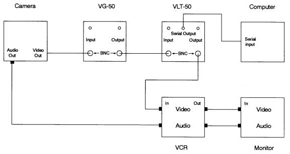
On
the back of both the VG-50 and VLT-50 there are 2 pairs of connectors. The top
pair are RCA connectors and are used for an audio input signal. Since we are
interested in a video signal, the bottom BNC connectors must be used. After
connecting the various components as shown above, you must also set the VG-50
and VLT-50 so that they generate the desired outputs. We recommend the following
settings:
VG-50
Settings:
Line
Select: Hold and 15/17 16/18
VLT-50
Settings:
Mode:
Hold
LTC Output: FWD/REV
Select: VITC
Search Offset: Off
When
all of the components are powered up, you can activate the time signal by first
moving the display toggle on the VG-50 to the right until the display on the
monitor shows the following:
T HH:MM:SS:FF Where:
HH is hours, MM is minutes, SS is seconds, and FF is video frames 0-29 (30
frames of video per second)
This
display is the actual time stamp that will be sent to the video tape and the
computer. Once the display is shown, you can start the time code generation by
moving the Mode toggle on the VG-50 to the right and releasing. At this point
the display should show the time stamp counting up. In the STISIM Drive data
file, the time stamp that is saved is the current value being output by the
VG-50. This way you do not have to restart the VG-50 before each run, STISIM
Drive simply uses whatever the current value that is being generated. In order
to save the time code data to the STISIM Data file, you must use the BSAV event.
HORITA
is a manufacturer of various video editing tools, and additional information
can be obtained at:
HORITA
Co., Inc.
Post Office Box 3993
Mission Viejo, CA 92690
(949) 489-0240
horita@horita.com
www.horita.com
There are several tools that are installed during the STISIM Drive installation process. These tools are located in a Tools directory within the STISIM Drive directory (Usually C:\STISIM\Tools). The various tools are included to help make your life easier when installing, running and trouble shooting your system. The tools that are included are:
CalPot32 - Program for calibrating and testing the control inputs. This program has its own help file to instruct you on how it works.
DDA06_Reset - This is a program for resetting the DDA06 card on systems with force feedback on the steering system. During computer startup, some systems (it is not sure why it happens on some and not others) cause the DDA06 card to come up with full voltage to each of the output pins, this causes the steering wheel to spin until the voltages are turned off or the steering system is turned off. We recommend that you place a shortcut to the DDA06_Reset program in your startup directory so that it is run when Windows initializes, this way the voltages will be set accordingly. We also recommend that you turn the steering system off until after Windows boots, that way the steering wheel does not spin, the DDA06 board gets reset then the power is turned on. There is no user interface with the DDA06_Reset program, you run it, it sets the voltages on the DDA06 card and then it exits. Before running the DDA06_Reset program, you should first configure your system using the CalPot32 program.
Gains_Config - This little utility is for customers who were using the older DOS version of STISIM and are converting over to STISIM Drive. This utility will allow you to convert your GAINS file into a STISIM Drive configuration file. Because of option changes and new definitions, it does not do a 100 percent conversion, but it is a good place to start. You will still need to go into the STISIM Drive configuration option in order to complete the setup. When you run the Gains_Config program the following dialog window will be displayed:
You simply enter the name of the GAINS file that you will be convert by either typing it into the text box provided or by browsing your disk after clicking on the disk drive symbol. Next, enter the name of the configuration file where the GAINS file data will be stored by either typing the file name in the text box provided or by browsing the disk using the disk drive symbol provided. Once the 2 names have been specified, clicking on the Convert button will create the specified configuration file containing the relevant information from the GAINS file that was specified. To exit the program, simply click on the Exit button.