


2.00b Toy Product Design
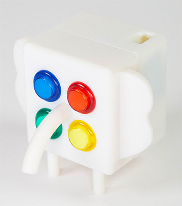
Let's Play - Toobers!
CAD 4Elephant in the Room
Learn by Doing!
The best way to learn CAD is to try it out yourself. Below are a series of videos that show one way to build an elephant.
You can pick and choose which steps you'd like to try. There is a brief description of the steps needed before each video, and then the video itself. See if you can follow along.
Filleting Edges
To fillet an edge is to round it over so that the edge is no longer sharp. We recommend that the fillet size for an edge not be more than 0.2". Open up the piece you want to work on, then follow the steps below.
We strongly recommend that you fillet all edges because the 3D printed edges are very sharp. You want to fillet the edges of the cube early in your design process, and definitely before adding any color, as the fillet will cut through any color you apply.
The steps to fillet an edge are:
- Select the Fillet tool (
 )
) -
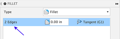
Select the edges that you want to fillet. You may select multiple
edges to apply the same fillet by clicking on each edge
sequentially. The FILLET dialog keeps track of how many edges are
selected. Click an edge again to de-select it.
-
Move the blue arrow to increase/decrease the amount of fillet or
type in a radius value.

-
Be sure to save your changes regularly. Click on the Save tool (
 ). The Save dialog will open. Provide a descriptive name for the version so that you know what modifications are in this version.
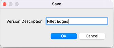
-
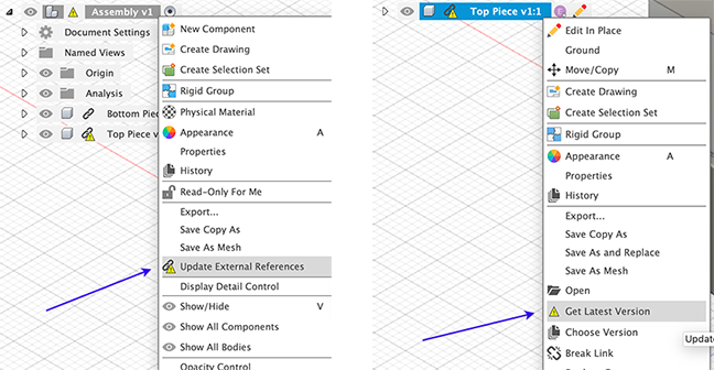
Go to the assembly and notice that there is now a warning that some components are out-of-date in the assembly (
 ) and the out-of-date parts are also marked (
 ). Right-click on the assembly and select Update External References to update the entire assembly, or you may right-click on an individual part and select Get Latest Version to update only that part. Do one of these to bring your recently saved changes into the assembly.
Watch the video for an example of how to fillet edges:
Modifying Button Spacing
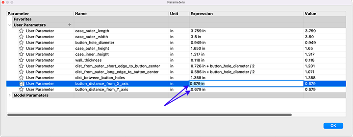
The space between the buttons is parameterized, so you can easily change the spacing by changing the value of the applicable parameters.
The steps modify button spacing are:
- Lock the X-axis and Y-axis.
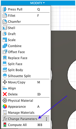
- Select Modify-->Change Parameters
-
Change the value for button_distance_from_X_axis or
button_distance_from_Y_axis
Watch the video for an example:
Adding Legs
Our next step is to add legs for our elephant. The video shows the creation of the front legs. Follow the same process for the back legs. We will be following the steps in the general Fusion 360 workflow: sketching a 2D circle, extruding the circle to make a 3D body, and then modifying the body with a fillet.
Watch the video for an example:
Adding Ears
Adding ears can be similar to adding legs, but we demonstrate a cut process.
Watch the video for an example:
Creating a Hole for a Nose
For the nose, we will be creating a registration mark in the casing and a peg in the nose part that will fit in the hole.
Watch the video for an example:
Creating the Nose
Here, the nose is created as a separate part with a peg to fit in the hole created above.
Watch the video for an example:
Attaching the Nose
In this video, we demonstrate how to put the nose together in the overall assembly.
Watch the video for an example:
Applying Color
Our elephant is done! But it could use a little color!
Watch the video for an example:
Once you've made the elephant, you may want to start with a new copy of the base assembly to customize your own design. You may create folders inside your named folder. For example, create a folder Elephant and then right-click on each of the files and select Move to move them into the Elephant folder. Then, you can create another folder and import the base assembly into there to start fresh.