2.00b Toy Product Design
Let's Play - Toobers!
PCB Assembly 4Actually Soldering!
It's time.
Hold the soldering iron tip to where the contact of the component meets the metal solder pad. Next, take the spool of solder, and touch some solder gently to the contact of the component. You should see a very nice cone form between the contact and the solder pad.

It's your time to shine. Go ahead and solder all the components to the PCB now! See you in a bit!
Made a mistake?
No worries! Happens all the time. If you need to remove solder, grab the solder wick (or the de-soldering braid) and simply place the end of the wick over the solder you want to remove and then place your heated solder tip over it. The braid heats up and encourages the solder to “wick” into it.
The other (more fun) tool we have is a solder sucker, which is a mini mechanically powered vacuum that can suck the solder up when it's still molten and remove it from your work piece.
(These are tools that you'll probably need to grab from the 'common' pile. Feel free to grab one to investigate.)
Tidy it Up!
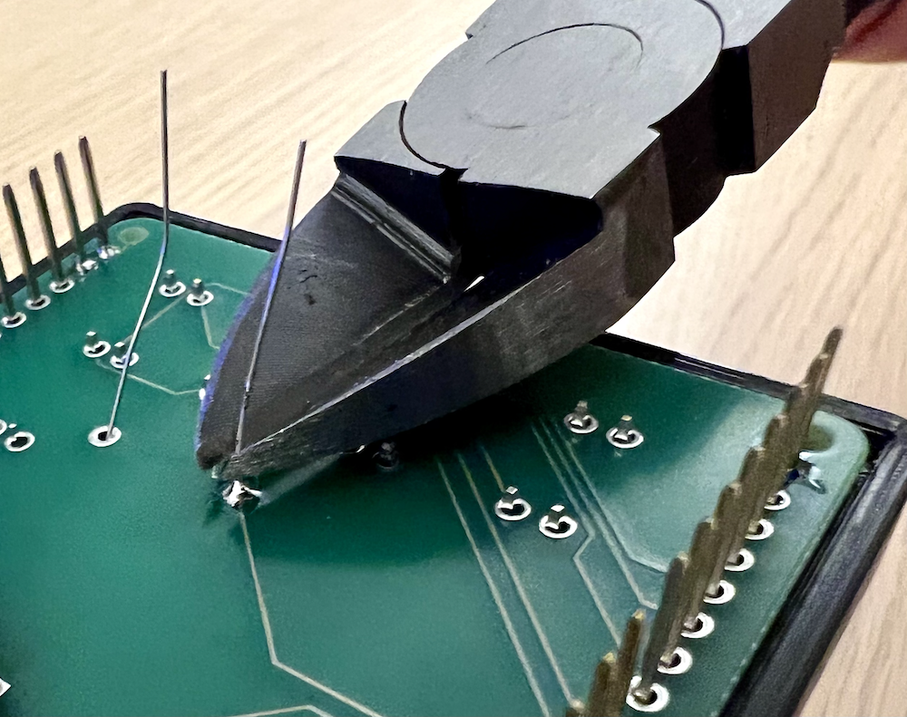
Use some flush cutters to trim off any excess wires or contacts. In this case, it should only be the 1KΩ resistor - but always a good practice!
DO NOT trim down the long female header pins. These NEED to extend beyond the PCB in order to sit into your Arduino later.
Soldering the 9V Battery Connector
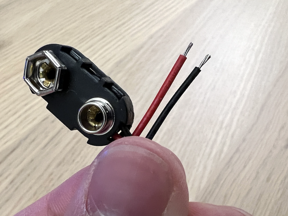
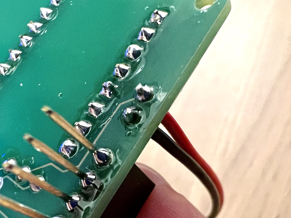
The battery connector is the final thing you'll be soldering. Place the two ends (strip them a tiny bit if they need to be exposed more and solder it like you did before. If you need another hand to help you hold the parts as you solder, you can use the clips on the left and right of the soldering iron (conveniently known as helping hands!)
The red wire should go into Vin (for power), and the black wire should go into Gnd
Check for Continuity
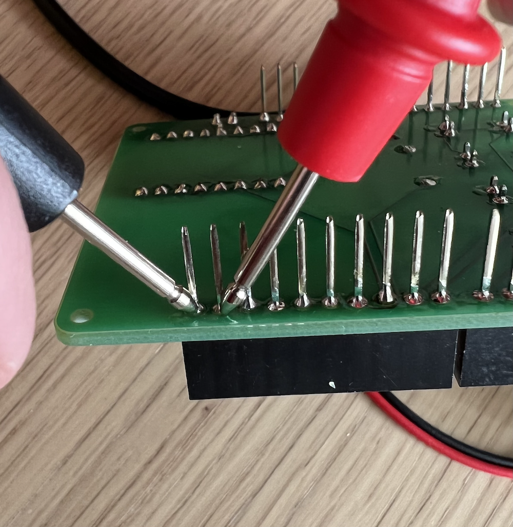
Take a moment to check for unwanted bridges/connections between adjacent pins, especially if you don't fully trust your soldering skills yet. To do this, you can use the multimeter tool. Turn your multimeter on and set it to the diode/speaker symbol. Place the red and black probes in the slots as shown below:
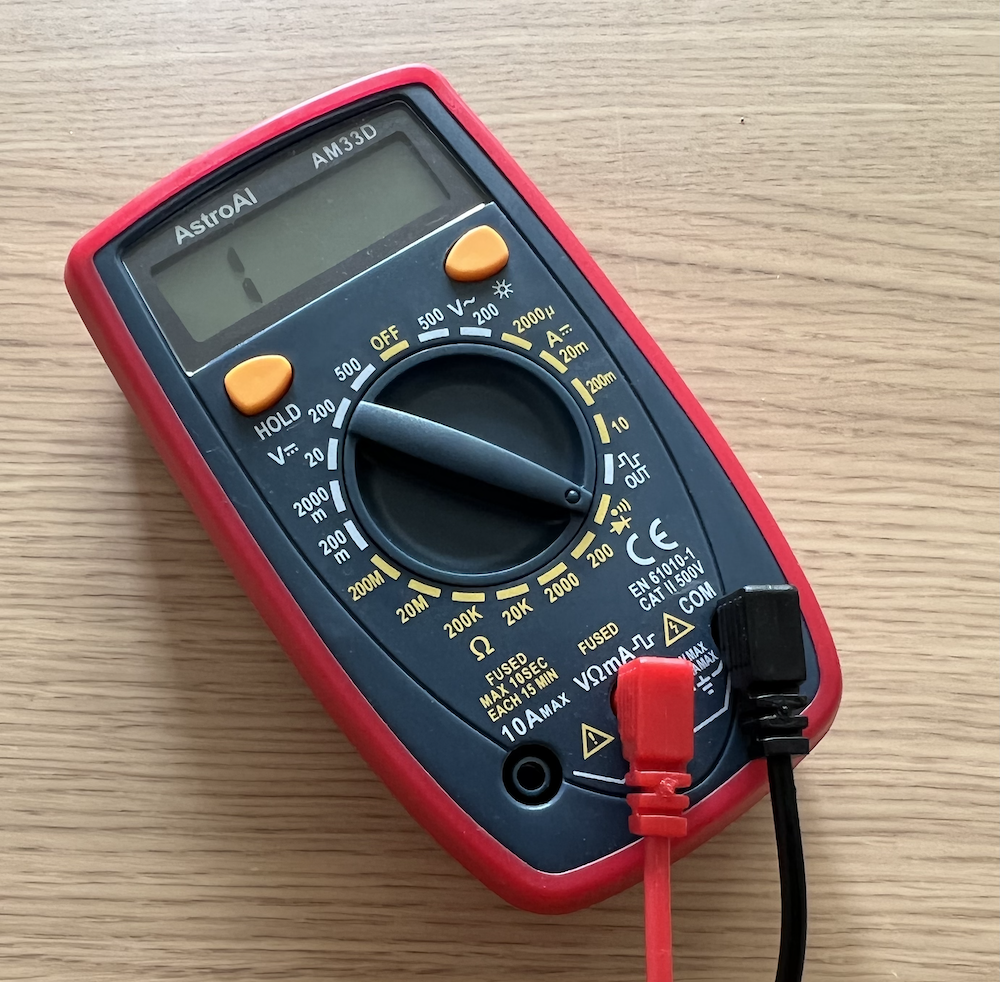
In this mode, the multimeter will make a beep if there is an electrical connection (continuity) between the two probes. You can also see the display show a 0 (or something close to 0) if it's a connection (no resistance). If there is an open circuit, you'll see a 1 digit on the far left.
To test for unwanted connections in your circuit, hold up each probe to a pin. If it beeps, you probably have too much solder and will need to remove some before proceeding (in order to break the connection.)