Wall Module: Electronics
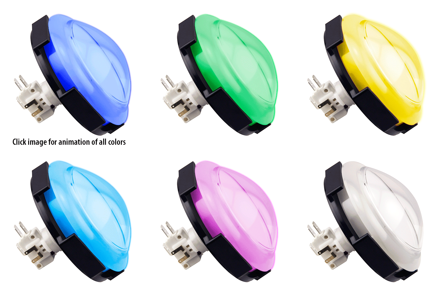
For the integration of the main interactive elements of the gameplay, we implemented in the front side of the wall the pushbuttons and light circuit paths, both of which serve as indicators of the gameplay. For the pushbutton, we implemented a commercially available button (from Suzohapp) which is RGB color-capable. We sought this implementation as a simple, cheap and easily replaceable solution for the pushbutton since it might get worn down from multiple plays. Additionally, the front wall implements addressable RGB LED strips (from Neopixel). These addressable Neopixel strips have the advantage of allowing us to control individual LEDs along the strip which will prove to be essential for the gameplay dynamics.
Suzohapp RGB LED with Microswitch

Adafruit NeoPixel Digital RGB LED Strip

On the back side of the wall, we integrated the “brain” of the gameplay, the Arduino Mega board, which is fully capable of integrating, synchronizing and operating the multiple electrical components of the gameplay. For ease of debugging and re-wiring, we established the electrical connections via breadboards (one for the buttons and another for the LED strips). In the breadboard dedicated to the buttons, a series of n-channel mosfets (black cap transistors in the diagram) were connected to the blue/red color connections of the Suzohapp button and the digital pins of the Arduino to control the ON/OFF state of these colors during the gameplay. Additionally, the micro-switch system of the button was connected to the 5V supply of the Arduino and a communication pin which signaled the Arduino when the buttons was pressed. Note from the diagram, that the 5V connections to each button required a 220 ohms resistor per button connection. For the breadboard with the LED strips, a simpler connection was required to the Arduino with only a connection to the PWM pin from the Arduino to each strip (intermediated by a 470 ohms resistor) to control the light dynamics of each strip. As a safety precaution to avoid the initial onrush of current from damaging the electrical components, a large capacitor (1000 µF) across the + and – terminals was added for each power supply. For the purposes of our presentation, we powered the Arduino directly form the USB computer connection but external power sources are also viable.
