Vacuum Internal Subassembly
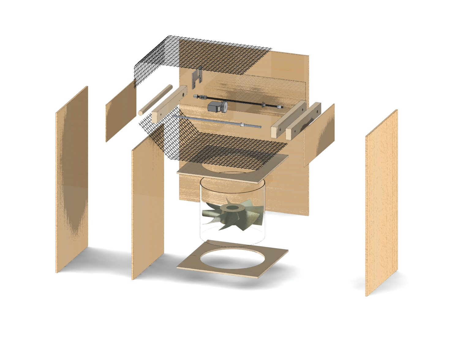
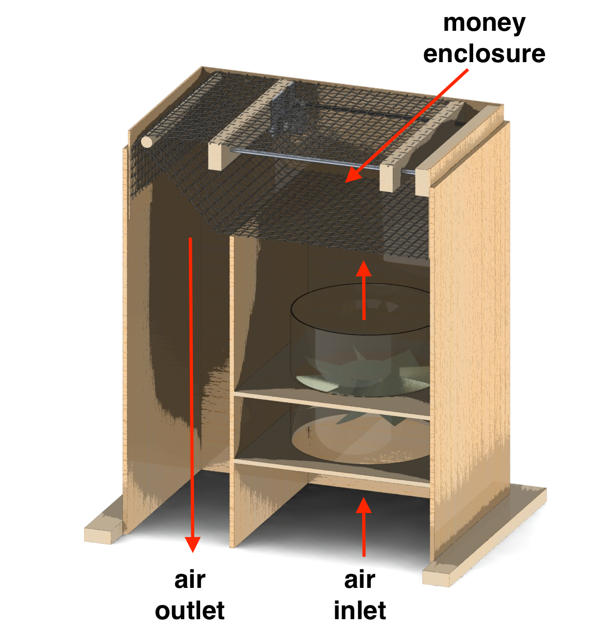
The render below reveals the overall structure of the internal subsystem. The front panel and support have been removed to take a look under-the-hood. The internal box is divided in three sections, the top enclosure where the bills are stored between a static, bottom mesh and a rolling top mesh, the bottom right section with the fan, where air is pulled in, and the bottom left section where air travells out of the box.
In the top section a metallic mesh is attached to a wood (beech or similar) structure, forming the floor where the bills are held at the beginning of the game or if the fan turns off (i.e. the players stop rotating the vacuum crank). The top mesh is attached to a driven horizontal-wood-member on one end and attached to a weight on the free end, that drops off at the far end. The horizontal support of the fixed, driven end of the top mesh has an enchored T-nut which allows a threaded rod to rotate within, causing a horizontal motion. The threaded rod is mechanically mated to a continuous rotation servo motor, which is sized to displace an inch of mesh in 7 seconds, or the full mesh cover in just over a minute.
In the bottom right section, a 120V 8" diameter fan will be anchored 5 inches from the bottom of an 11"*11" enclosure (cross section of subsystem is 11" * 17"). This fan is able to drive over 3X the flowrate of the previous design, and given the separation of the subsystem from the ground (refer to General Vacuum and Vacuum Base for details) there is an improved air inlet. Note that the transparency of the fan enclosure (translucent cylinder) has been altered (this cover is metallic).The fan power will be powered by a switching relay, controlled by the rotation of a crank using a reflective IR sensor (see BOM note below).
The bottom left section is simply a channel for air to leave the enclosed space. This channel radically increases the airflow throughout the box, as the fan works across a smaller pressure drop.
This design has been modified to increase the travel length of the mesh (i.e. the servo and the support member have been shifted leftwards, closer to the location where the mesh drops off) which reduces the probability of bills getting stuck on the top, horizontal mesh. Two solutions are being evaluated (additional sketch modelling) to fully resolve this issue: (1) elongate the internal subsystem under the clear cover where the bills appear such that the mechanism and the remaining net are strictly under the black cover (2) add a net slanted at a 45 degree angle that forces the bills back to the storage compartment.