2.810 Manufacturing Processes and Systems
Welcome to 2.810
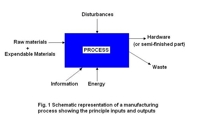
This course is about manufacturing processes. At one level manufacturing processes can be thought of as the methods by which we convert raw or unfinished materials into useful hardware. In fact, often the various manufacturing processes are categorized by the type of material which is converted, e.g. metal removal processes, polymer processes, ceramics processes, etc. This view is represented schematically in Fig. 1.
The processing of materials in machines can be analyzed using scientific and engineering principles (heat transfer, solid, and fluid mechanics etc.) to better understand these processes, to optimize and control them, and to maximize their output. In this course, we will use results from these analyses to understand manufacturing processes. We will identify the fundamental physical mechanisms for each process considered, and show the relationship between these mechanisms and the behavior of the process in terms of rate, quality, cost, and flexibility. To do this we may have to get into some mathematical derivations, particularly in the area of heat transfer, but in general the emphasis will be on identifying critical physical phenomena and describing the appropriate scaling laws.
In addition to material flow through the process, we may also consider both the energy flow and the information flow. Energy is required to do the work of disturbing and, in some cases, reestablishing atomic and molecular bonds in order to change the shape, surface, and microstructure of the material we are processing. Analysis in this area is also quite amenable to engineering principles.
Information of several types is required in materials processing including; 1) production information (how many parts to make, when etc.), 2) parameter setting information (temperature, pressure, time, etc.) and 3) basic structural and shape information. This later form of information is often supplied in two distinct manners; 1) sequentially (a little bit at a time) or 2) in parallel (all at once). The sequential processes generally make a part by either adding (e.g. rapid prototyping) or subtraction (e.g. machining) material a little at a time. Usually the shape information of these processes is embodied in a software program which drives a positioning system with a focused end effector. In contrast, parallel processes usually use hard tooling to embody the shape information for the part. The shape information is then imparted almost instantaneously and everywhere for the part. This group of processes include; injection molding, casting, forging etc. When the resulting part requires very little post-processing, the parallel process can also be called net shape . We will use the broad categories of sequential (including additive and subtractive) and parallel(including net shape processes) to generalize about the various characteristics of a process.
Note that parameter setting information (the second in our list above) can be obtained from: experience, handbooks, engineering models, and designed experiments. You will get first hand parameter setting experience when you and/or members of your group operate the various processes we use in this course. Located on the first floor of Building 35 in the Laboratory for Manufacturing and Productivity you will find the machines to be used in your group car project, including; 1) a 3 axis CNC Vertical Milling Machine, 2) a 30 ton injection molding machine, and 3) a thermoforming machine. Production type information, the first in the list above, will be dealt with at the system level, which will be discussed shortly.
Also note that in Fig. 1 we have indicated the possibility of disturbances to the process. These may come as variation in the various inputs, as well as variation in the environment, operator, machine and methods. The identification of, and elimination of disturbances is critical to manufacturing process engineering. At this point we will also introduce the notion of feedback information related to the performance of the process.
Viewed in another way, manufacturing processes are part of a system to make competitive products. In fact, they are at the center of the system for the creative development of products. This idea is shown schematically in Fig. 2.
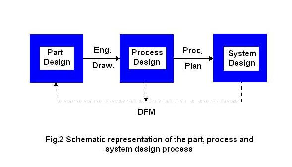
Here we are looking at the three steps to design a new product including part design, process design and system design. To have a successful manufacturing enterprise, each one of these steps must be done well. In this course we will consider all three steps for a few well defined examples. Of course, our emphasis will be on the process, but we will clearly show the interconnection and interdependence of the three steps. Of critical importance in this sequence are the communication links between part and process, and process and system. These are marked in the figure as, 1) the engineering drawing, and 2) the process plan, respectively. The importance of these two vehicles for understanding processes can not be overstated. We will use them repeatedly. Feedback to part design in order to alleviate manufacturing problems at either the process or system level, is indicated by the dash line marked DFM (Design for Manufacturing). In this course we will consider the manufacturing cell as the representative unit for the system. Hence we will show how one goes from part design, through process design to cell design and back again for the volume production of a part or an assembly.
Our goal for 2.810 is to develop both of the process views outlined above. In order to do this in our allotted time we will focus primarily on 5 processes; assembly, machining, casting, injection molding, and thermoforming. You will receive hands on experience for each of these processes through your work on the group project. More information on the goals of the course and the project can be found in separate sections of this web site.
Hope to see you in class.
Tim Gutowski