

What are Free Body Diagrams?

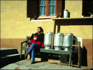
Notice how the person, cans and upper shelf dematerialize and are replaced
by vectors. The FBD at the end of the movie is not complete. What is missing?
Everything that is needed to solve a force system is included
on the FBD. Free body diagrams may not seem necessary in the relatively
simple current applications, but as problems become more complex, their
usefulness increases.

The following is the process for determining the reaction at the wall for
a cantilever beam. A FBD is first drawn of the beam. Next, cut the beam
free from the wall and replace the wall with the forces that were supporting
the beam at the wall before it was cut free. These forces are unknown, but
they are the only forces that can keep the beam in equilibrium. They are
identical to the internal forces in the beam at that point before it was
cut. The internal forces in the beam before it was cut free from its support
are also determined when the forces which will keep, or put, the FBD in
equilibrium are found.
A fixed support will resist translation in all directions
and rotation (moment). The FBD must show all of these directions. The principles
of equilibrium can always be used to solve a FBD. In the FBD above Sum Fy = 2K and Sum Fx = 0. The 2K forces
(load and vertical reaction force) cause a counter-clockwise couple of 10
K-FT which must be resisted by a moment on the end of the cut section of
10 K-FT acting in a clockwise direction.

This is an illustration of three different structural systems which have
one 100 pound load and one 150 pound load acting on them at exactly the
same point. They are also supported with a roller support at the left and
pinned support at the right. Each one could be a structure made of any type
of material.....wood, steel, bamboo, or perhaps paper.
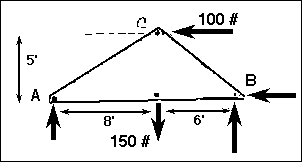
This is a Free Body Diagram of these three systems which has been drawn
to represent the force system. Note how all of the internal structure has
been removed from this representation. The internal arrangement does not
matter for the determination of the supporting reactions! AND, if the supporting
and loading geometries are the same, the external reactions will alsways
remain the same.
The Umbrian Street Lamp 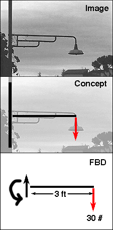
This is a street lamp that is commonly found in Umbria, Italy. It looks
like many lamps found all over the world. The three photos illustrate how
the free body diagram for this structure should be conceived. The first
step is to dematerialize the lamp. Identify the center of the body and draw
this as a straght line. The only identifieable weight is the lamp, so this
is drawn as a vector as indicated. The next step is to determine what is
required at the other end of the lamp to maintain equilibrium; what is needed
to keep the lamp from spinning off into space? These forces (including the
moment) are drawn as indicated. What is missing from this illustration?
The magnitudes of the moment and force at the left side should be included
in a complete free body diagram.
The Verona Column 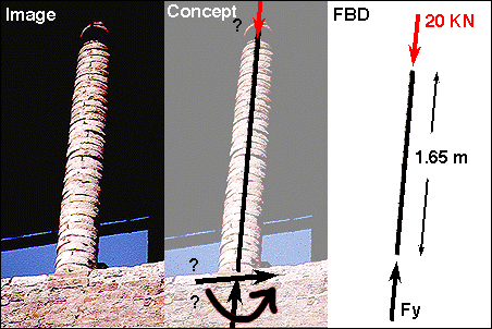
There are many situations in which the exact conditions of the end restraints
are not able to be determined in the first glance. The materiality and relative
stiffness of the elements which are being supported/connected provide clues
as to the actual behavior.
This is a thin brick column supporting a wooden canopy at the old castle
in Verona, Italy. How is this element connected to the wall below?
Most likely one would model this behavior as a simple connection. The masonry
would have a very difficult time transferring moments since it cannot develop
the required tensile half of the couple. The mortar would also most likely
yield if a lateral load of significant force were to be applied. However,
one could argue that the column can, and certainly does, resist a small
amount of lateral load. And, due to the force of gravity pulling each brick
down there could be the possibility for the base to begin to resist a moderate
moment as long as the tensile force does not exceed the compressive force
due to the self-weight of the structure. So, where does this leave the FBD?
In the hands of the designer to make a choice on the type of model that
he/she desires.... What is the correct model? It depends.
The Harbor Crane 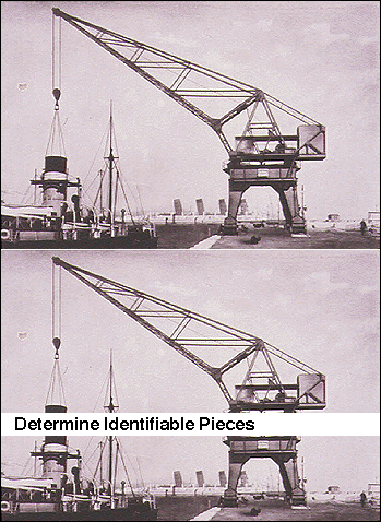
When confronted with what appears to be a complex prolblem, the first thing
to do is to SIMPLIFY!!! Determine the identifiable pieces. Look for significant
changes in the structural morphology. Turn the image upside down if need
be in order to attempt to dematerialze the problem.
In this case, the crane must be divided into at least two recognizable pieces.
It has a trussed upper structure (A) and a rigid frame lower structure (B).
We can split the structures into these two parts because we can also recognize
that the upper part must be able to rotate while the lower part remains
"stable" or at the very least remains in place. Two significant
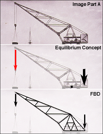
weights, or forces, can be identified acting on part A; the weight of the
hoisted load and the large concrete block counter-balance. Notice the relative
magnitudes of the force vectors. If the actual magnitude of forces are unknown, this is one way in which these values can be represented.
Note also that some parts of the actual built form of the crane have been neglected in the upper part. There is
a series of machines which occupy the platform above the circular swivel track. These are not really of
concern in this anaysis unless they are permanent AND of considerable weight. If they are NOT considered, then their
location at the center of the whole crane adds a bit of stability to the overall system. Thus, smaller items which might or
might not be present are usually neglected.
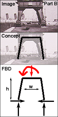
Part B consists of a heavy, solid plate steel rigid frame. It seems to have feet at the bottom of each
"leg" that provide the "footing." The free body diagram is drawn passing through the center of gravity of the
section. There are times when the location of the center of gravity is actualy unknown. When this is the
case, then it is necessary to make a "best guess" as to its location. Once this is completed, it can be tested as
to its "correctness" by the logic of the resulting diagram. There are times when the Free body diagram does not seem to
represent anything close to the built form.
Note that the "action" on this, the lower frame, consists of both a Force
and a Moment. What created these two seperate forces? Why is there both a moment and a vertical load? Why not only a
vertical load? or only a moment? In order to analyze this part of the frame we must consider ALL of the actions which come "from above."
This is essentially a moment which has been generated by the tendency of the crane to tip. BUT, the vertical load of the
bit being moved MUST also at some point get to the ground. It does so through the frame. Try analyzing the frame with
assumed values.
What influence does this have on the total
capacity of the crane? How might this crane fail? What element might fail
first?
![]()
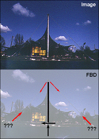
How would the FBD be completed for the anchor blocks for Frei Otto's
tent structure?
Seward, Derek. Understanding Structures. Macmillan Press (London). 1994. pp. 18 - 24.