
11.8
Forces on Microscopic Electric and Magnetic Dipoles
The energy principle was used in the preceding sections to derive the macroscopic forces on polarizable and magnetizable materials. The same principle can also be applied to derive the force distributions, the force densities. For this purpose, one needs more than a purely electromagnetic description of the system. In order to develop the simple model for the force density distribution, we need the expression for the force on an electric dipole for polarizable media, and on a magnetic dipole for magnetizable media. The force on an electric dipole will be derived simply from the Lorentz force law. We have not stated a corresponding force law for magnetic charges. Even though these are not found in nature as isolated charges but only as dipoles, it is nevertheless convenient to state such a law. This will be done by showing how the electric force law follows from the energy principle. By analogy a corresponding law on magnetic charges will be derived from which the force on a magnetic dipole will follow.
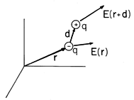
Figure 11.8.1 An electric dipole experiences a net electric force if the positive charge q is subject to an electric field E (r + d) that differs from E(r) acting on the negative charge q.
Force on an Electric Dipole
The force on a stationary electric charge is given by the Lorentz law with v = 0.
A dipole is the limit of two charges of equal magnitude and opposite sign spaced a distance d apart, in the limit
with p being finite. Charges q of opposite polarity, separated by the vector distance d, are shown in Fig. 11.8.1. The total force on the dipole is the sum of the forces on the individual charges.
Unless the electric field at the location r + d of the positive charge differs from that at the location r of the negative charge, the separate contributions cancel.
In order to develop an expression for the force on the dipole in the limit where the spacing d of the charges is small compared to distances over which the field varies appreciably, (2) is written in Cartesian coordinates and the field at the positive charge expanded about the position of the negative charge. Thus, the x component is
The first and last terms cancel. In more compact notation, this expression is therefore
where we have identified the dipole moment p
qd. The other force components follow in a similar fashion, with y and z playing the role of x. The three components are then summarized in the vector expression
The derivation provides an explanation of how p

E is evaluated in Cartesian coordinates. The i-th component of (5) is obtained by dotting p with the gradient of the i-th component of E.
Illustration. Force on a Dipole
Suppose that a dipole finds itself in the field
which is familiar from Example 4.1.1. It follows from (5) that the force is
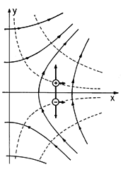
According to this expression, the y-directed dipole on the x axis in Fig. 11.8.2 experiences a force in the x direction. The y-directed force is zero because Ey is the same at the respective locations of the charges. The x-directed force exists because Ex goes from being positive just above the x axis to negative just below. Thus, the x-directed contributions to the force of each of the charges is in the same direction.
Figure 11.8.2 Dipole having y direction and positioned on the x axis in field of (6) experiences force in the x direction.
Force on Electric Charge Derived from Energy Principle
The force on an electric charge is stated in the Lorentz law. This law is also an ingredient in Poynting's theorem, and in the identification of energy and power flow. Indeed, EJu was recognized from the Lorentz law as the power density imparted to the current density of unpaired charge. The energy principle can be used to derive the force law on a microscopic charge "in reverse". This seems to be the hard way to obtain the Lorentz law of force on a stationary charge. Yet we go through the derivation for three reasons.
shown to be consistent with the Lorentz force on a stationary charge.
(a) The derivation of force from the EQS energy principle is (b) The derivation shows that the field can be produced by permanently polarized material objects, and yet the energy principle can be employed in a straightforward manner.
(c) The same principle can be applied to derive the microscopic MQS force on a magnetic charge.
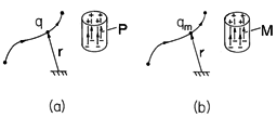
Let us consider an EQS field produced by charge distributions and permanent polarizations Pp in free space as sketched in Fig. 11.8.3a. By analogy, we will then have found the force on a magnetic charge in the field of a permanent magnet, Fig. 11.8.3b. The Poynting theorem identifies the rate of energy imparted to the polarization per unit volume as
Figure 11.8.3 (a) Electric charge brought into field created by permanent polarization. (b) Analogous magnetic charge brought into field of permanent magnet. Because Pp is a permanent polarization,
Pp /
t = 0, and the permanent polarization does not contribute to the change in energy associated with introducing a point charge. Hence, as charge is brought into the vicinity of the permanent polarization, the change of energy density is
where
stands for the differential change of
o E. The change of energy is
where V includes all of space. The electroquasistatic E field is the negative gradient of the potential
Introducing this into (10), one has
where we have "integrated by parts," using an identity.7
7 (
)
A =

(A
) - (

A)

The first integral can be written as an integral over the surface enclosing the volume V. Since V is all of space, the surface is at infinity. Because E
vanishes at infinity at least as fast as 1/r3 (1/r2 for E, 1/r for
, where r is the distance from the origin of a coordinate system mounted within the electroquasistatic structure), the surface integral vanishes. Now
from Gauss' law, where

u is the change of unpaired charge. Thus, from (12),
so the change of energy is equal to the charge increment

u dv introduced at r times the potential
at r, summed over all the charges.
Suppose that one introduces only a small test charge q, so that
u dv = q at point r. Then
The change of energy is the potential
at the point at which the charge is introduced times the charge. This form of the energy interprets the potential of an EQS field as the work to be done in bringing a charge from infinity to the point of interest.
If the charge is introduced at r +
r, then the change in total energy associated with introducing that charge is
Introduction of a charge q at r, subsequent removal of the charge, and introduction of the charge at r +
r is equivalent to the displacement of the charge from r to r +
r. If there is a net energy decrease, then work must have been done by the force f exerted by the field on the charge. The work done by the field on the charge is
and therefore
Thus, the Lorentz law for a stationary charge is implied by the EQS laws.
Before we attack the problem of force on a magnetic charge, we explore some features of the electroquasistatic case. In (17), q is a small test charge. Electric test charges are available as electrons. But suppose that in analogy with the magnetic case, no free electric charge was available. Then one could still produce a test charge by the following artifice. One could polarize a very long-thin rod of cross-section a, with a uniform polarization density P along the axis of the rod (Sec. 6.1). At one end of the rod, there would be a polarization charge q = Pa, at the other end there would be a charge of equal magnitude and opposite sign. If the rod were of very long length, while the end with positive charge could be used as the "test charge," the end of opposite charge would be outside the field and experience no force. Here the charge representing the polarization of the rod has been treated as unpaired.
We are now ready to derive the force on a magnetic charge.
Force on a Magnetic Charge and Magnetic Dipole
The attraction of a magnetizable particle to a magnet is the result of the force exerted by a magnetic field on a magnetic dipole. Even in this case, because the particle is macroscopic, the force is actually the sum of forces acting on the microscopic atomic constituents of the material. As pointed out in Secs. 9.0 and 9.4, the magnetization characteristics of macroscopic media such as the iron particle relate back to the magnetic moment of molecules, atoms, and even individual electrons. Given that a particle has a magnetic moment m as defined in Sec. 8.2, what is the force on the particle in a magnetic field intensity H? The particle can be comprised of a macroscopic material such as a piece of iron. However, to distinguish between forces on macroscopic media and microscopic particles, we should consider here that the force is on an elementary particle, such as an atom or electron.We have shown how one derives the force on an electric charge in an electric field from the energy principle. The electric field could have been produced by permanently polarized dielectric bodies. In analogy, one could produce a magnetic field by permanently magnetized magnetic bodies. In the EQS case, the test charge could have been produced by a long, uniformly and permanently polarized cylindrical rod. In the magnetic case, an "isolated" magnetic charge could be produced by a long, uniformly and permanently magnetized rod of cross-sectional area a. If the magnetization density is M, then the analogy is
where, for the uniformly magnetized rod, and the magnetic charge
is located at one end of the rod, the charge -qm at the other end of the rod (Example 9.3.1). The force on a magnetic charge is thus, in analogy with (18),
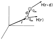
which is the extension of the Lorentz force law for a stationary electric charge to the magnetic case. Of course, the force on a dipole is, in analogy to (5) (see Fig. 11.8.4),
where m is the magnetic dipole moment.
Figure 11.8.4 Magnetic dipole consisting of positive and negative magnetic charges qm. We have seen in Example 8.3.2 that a magnetic dipole of moment m can be made up of a circulating current loop with magnitude m = ia, where i is the current and a the area of the loop. Thus, the force on a current loop could also be evaluated from the Lorentz law for electric currents as
with i the total current in the loop. Use of vector identities indeed yields (22) in the MQS case. Thus, this could be an alternate way of deriving the force on a magnetic dipole. We prefer to derive the law independently via a Lorentz force law for stationary magnetic charges, because an important dispute on the validity of the magnetic dipole model rested on the correct interpretation of the force law[1-3]. While the details of the dispute are beyond the scope of this textbook, some of the issues raised are fundamental and may be of interest to the reader who wants to explore how macroscopic formulations of the electrodynamics of moving media based on magnetization represented by magnetic charge (Chap. 9) or by circulating currents are reconciled.
The analogy between the polarization and magnetization was emphasized by Prof. L. J. Chu[2], who taught the introductory electrical engineering course in electromagnetism at MIT in the fifties. He derived the force law for moving magnetic charges, of which (21) is the special case for a stationary charge. His approach was soon criticized by Tellegen[3], who pointed out that the accepted model of magnetization is that of current loops being the cause of magnetization. While this in itself would not render the magnetic charge model invalid, Tellegen pointed out that the force computed from (23) in a dynamic field does not lead to (22), but to
Because the force is different depending upon whether one uses the magnetic charge model or the circulating current model for the magnetic dipole, so his reasoning went, and because the circulating current model is the physically correct one, the magnetic charge model is incorrect. The issue was finally settled[4] when it was shown that the force (24) as computed by Tellegen was incorrect. Equation (23) assumes that i could be described as constant around the current loop and pulled out from under the integral. However, in a time-varying electric field, the charges induced in the loop cause a current whose contribution precisely cancels the second term in (24). Thus, both models lead to the same force on a magnetic dipole and it is legitimate to use either model. The magnetic model has the advantage that a stationary dipole contains no "moving parts," while the current model does contain moving charges. Hence the circulating current formalism is by necessity more complicated and more likely to lead to error.
Comparison of Coulomb's Force on an Electron to the Force on its Magnetic Dipole
Why is it possible to accurately describe the motions of an electron in vacuum by the Lorentz force law without including the magnetic force associated with its dipole moment? The answer is that the magnetic dipole effect on the electron is relatively small. To obtain an estimate of the magnitude of the magnetic dipole effect, we compare the forces produced by a typical (but large) electric field achievable without electrical breakdown in air on the charge e of the electron, and by a typical (but large) magnetic field gradient acting on the magnetic dipole moment of the electron. Taking for E the value 106 V/m, with e
1.6 x 10⁻¹⁹ coulomb,
A B of 1 tesla (10,000 gauss) is a typical large flux density produced by an iron core electromagnet. Let us assume that a flux density variation of this order can be produced over a distance of 1 cm, which is, in practice, a rather high gradient. Yet taking this value and a moment of one Bohr magneton (9.0.1), we obtain from (22) for the force on the electron
Note that the electric force associated with the net charge is much greater than the magnetic one due to the magnetic dipole moment. Because of the large ratio fe/fm for fields of realistic magnitudes, experiments designed to detect magnetic dipole effects on fundamental particles did not utilize particles having a net charge, but rather used neutral atoms (most notably, the Stern-Gerlach experiment8.
8W. Gerlach and O. Stern, "Uber die Richtungsquantelung im Magnetfeld," Ann. d. Physik, 4th series, Vol. 74, (1924), pp. 673-699.). Indeed, a stray electric field on the order of 10-6 V/m would deflect an electron as strongly as a magnetic field gradient of the very large magnitude assumed in calculating (26).
The small magnetic dipole moment of the electron can become very important in solid matter because macroscopic solids are largely neutral. Hence, the forces exerted upon the positive and negative charges within matter by an applied electric field more or less cancel. In such a case, the forces on the electronic magnetic dipoles in an applied magnetic field can dominate and give rise to the significant macroscopic force observed when an iron filing is picked up by a magnet.
Example 11.8.1. Magnetization Force on a Macroscopic Particle
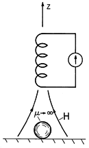
Suppose that we wanted to know the force exerted on an iron particle by a magnet. Could the microscopic force, (22), be used? The energy method derivation shows that, provided the particle is surrounded by free space, the answer is yes. The particle is taken as being spherical, with radius R, as shown in Fig. 11.8.5. It is assumed to have such a large magnetizability that its permeability can be taken as infinite. Further, the radius R is much smaller than other dimensions of interest, especially those characterizing variations in the applied field in the neighborhood of the particle.
Figure 11.8.5 By dint of its field gradient, a magnet can be used to pick up a spherical magnetizable particle. Because the particle is small compared to dimensions over which the field varies significantly, we can compute its moment by approximating the local field as uniform. Thus, the magnetic potential is determined by solving Laplace's equation in the region around the particle subject to the conditions that H be the uniform field Ho at "infinity" and
be constant on the surface of the particle. The calculation is fully analogous to that for the electric potential surrounding a perfectly conducting sphere in a uniform electric field. In the electric analog, the dipole moment was found to be (6.6.5), p = 4

o R3 E. Therefore, it follows from the analogy provided by (19) that the magnetic dipole moment at the particle location is
Directly below the magnet, H has only a z component. Thus, the dipole moment follows from (27) as
Evaluation of (22) therefore gives
where Hz and its derivative are evaluated at the location of the particle.
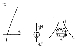
A typical axial distribution of Hz is shown in Fig. 11.8.6 together with two pictures aimed at gaining insight into the origins of the magnetic dipole force. In the first, the dipole is again depicted as a pair of magnetic monopoles, induced to form a moment collinear with the H. Because the field is more intense at the north pole of the particle than at the south pole, there is then a net force.
Figure 11.8.6 In an increasing axial field, the force on a dipole is upward whether the dipole is modeled as a pair of magnetic charges or as a circulating current. Alternatively, suppose that the dipole is actually a circulating current, so that the force is given by (23). Even though the energy argument makes it clear that the force is again given by (22), the physical picture is different. Because H is solenoidal, an intensity that increases with z implies that the field just off axis has a component that is directed radially inward. It is this radial component of the flux density crossed with the current density that results in an upward force on each segment of the loop.
