A three-dimensional vector field A (r) is specified by three components that are, individually, functions of position. It is difficult enough to plot a single scalar function in three dimensions; a plot of three is even more difficult and hence less useful for visualization purposes. Field lines are one way of picturing a field distribution.
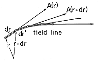
A field line through a particular point r is constructed in the following way: At the point r, the vector field has a particular direction. Proceed from the point r in the direction of the vector A (r) a differential distance dr. At the new point r + dr, the vector has a new direction A (r + dr). Proceed a differential distance dr' along this new (differentially different) direction to a new point, and so forth as shown in Fig. 2.7.1. By this process, a field line is traced out. The tangent to the field line at any one of its points gives the direction of the vector field A(r) at that point.
The magnitude of A (r) can also be indicated in a somewhat rough way by means of the field lines. The convention is used that the number of field lines drawn through an area element perpendicular to the field line at a point r is proportional to the magnitude of A (r) at that point. The field might be represented in three dimensions by wires.
If it has no divergence, a field is said to be solenoidal. If it has no curl, it is irrotational. It is especially important to conceptualize solenoidal and irrotational fields. We will discuss the nature of irrotational fields in the following examples, but become especially in tune with their distributions in Chap. 4. Consider now the "wire-model" picture of the solenoidal field.
Single out a surface with sides formed of a continuum of adjacent field lines, a "hose" of lines as shown in Fig. 2.7.2, with endfaces spanning across the ends of the hose. Then, because a solenoidal field can have no net flux out of this tube, the number of field lines entering the hose through one endface must be equal to the number of lines leaving the hose through the other end. Because the hose is picked arbitrarily, we conclude that a solenoidal field is represented by lines that are continuous; they do not appear or disappear within the region where they are solenoidal.

The following examples begin to develop an appreciation for the attributes of the field lines associated with the divergence and curl.
Example 2.7.1. Fields with Divergence but No Curl (Irrotational but Not Solenoidal)
The spherical region r < R supports a charge density
=
o r/R. The exterior region is free of charge. In Example 1.3.1, the radially symmetric electric field intensity is found from the integral laws to be
In spherical coordinates, the divergence operator is (from Table I)
Thus, evaluation of Gauss' differential law, (2.3.1), gives
which of course agrees with the charge distribution used in the original derivation. This exercise serves to emphasize that the differential laws apply point by point throughout the region.
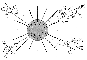
The field lines can be sketched as in Fig. 2.7.3. The magnitude of the charge density is represented by the density of + (or -) symbols.
Figure 2.7.3. Spherically symmetric field that is irrotational. Volume elements Va and Vc are used with Gauss' theorem to show why field is solenoidal outside the sphere but has a divergence inside. Surface elements Cb and Cd are used with Stokes' theorem to show why fields are irrotational everywhere. Where in this plot does the field have a divergence? Because the charge density has already been pictured, we already know the answer to this question. The field has divergence only where there is a charge density. Thus, even though the field lines are thinning out with increasing radius in the exterior region, at any given point in this region the field has no divergence. The situation in this region is typified by the flux of E through the "hose" defined by the volume Va. The field does indeed decrease with radius, but the cross-sectional area of the hose increases so as to exactly compensate and maintain the net flux constant.
In the interior region, a volume element having the shape of a tube with sides parallel to the radial field can also be considered, volume Vc. That the field is not solenoidal is evident from the fact that its intensity is least over the cross-section of the tube having the least area. That there must be a net outward flux is evidence of the net charge enclosed. Field lines originate inside the volume on the enclosed charges. Are the field lines in Fig. 2.7.3 irrotational? In spherical coordinates, the curl is
and it follows from a substitution of (1) that there is no curl, either inside or outside. This result is corroborated by evaluating the circulation of E for contours enclosing areas
a having normals in any one of the coordinate directions. [Remember the definition of the curl, (2.4.2).] Examples are the contours enclosing the surfaces Sb and Sd in Fig. 2.7.3. Contributions to the C" and C"' segments vanish because these are perpendicular to E, while (because E is independent of
and
) the contribution from one C' segment cancels that from the other.
Example 2.7.2. Fields with Curl but No Divergence (Solenoidal but Not Irrotational)
A wire having radius R carries an axial current density that increases linearly with radius. Ampère's integral law was used in Example 1.4.1 to show that the associated magnetic field intensity is
Where does this field have curl? The answer follows from Ampère's law, (2.6.2), with the displacement current neglected. The curl is the current density, and hence restricted to the region r < R, where it tends to be concentrated at the periphery. Evaluation of the curl in cylindrical coordinates gives a result consistent with this expectation.
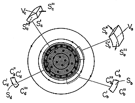
The current density and magnetic field intensity are sketched in Fig. 2.7.4. In accordance with the "wire" representation, the spacing of the field lines indicates their intensity. A similar convention applies to the current density. When seen "end-on," a current density headed out of the paper is indicated by \odot, while \otimes indicates the vector is headed into the paper. The suggestion is of the vector pictured as an arrow, with the symbols representing its tip and feathers, respectively.
Figure 2.7.4. Cylindrically symmetric field that is solenoidal. Volume elements Va and Vc are used with Gauss' theorem to show why the field has no divergence anywhere. Surface elements Sb and Sd are used with Stokes' theorem to show that the field is irrotational outside the cylinder but does have a curl inside. Can the azimuthally directed field vary with r (a direction perpendicular to
) and still have no curl in the outer region? The integration of H around the contour Cb in Fig. 2.7.4 shows why it can. The contours Cb' are arranged to make ds perpendicular to H, so that H
ds = 0 there. Integrations on the segments Cb"' and Cb" cancel because the difference in the length of the segments just compensates the decrease in the field with radius.
In the interior region, a similar integration surely gives a finite result. On the contour Cd, the field is larger on the outside leg where the contour length is larger, so it is clear that the curl must be finite. Of course, this field shape simply reflects the presence of the current density.
The field is solenoidal everywhere. This can be checked by taking the divergence of (5) in each of the regions. In cylindrical coordinates, Table I gives
The flux tubes defined as incremental volumes Va and Vc in Fig. 2.7.4, in the exterior and interior regions, respectively, clearly sustain no net flux through their surfaces. That the field lines circulate in tubes without originating or disappearing in certain regions is the hallmark of the solenoidal field.
It is important to distinguish between fields "in the large" (in terms of the integral laws written for volumes, surfaces, and contours of finite size) and "in the small" (in terms of differential laws). To this end, consider some questions that might be raised.
Is it possible for a field that has no divergence at each point
on a closed surface S to have a net flux through that surface?
Example 2.7.1 illustrates that the answer is yes. At each point on a
surface S that encloses the charged interior region, the divergence of
 oE is zero. Yet integration of
  o E
o E  da over
such a surface gives a finite value, indeed, the net charge enclosed.
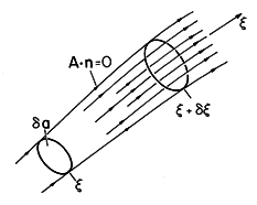
The divergence can be viewed as a weighted derivative along the
direction of the field, or along the field "hose." With  a defined as
the cross-sectional area of such a tube having sides parallel to the
field
  oE, as shown in Fig. 2.7.5, it follows from (2.1.2) that
the divergence is

The minus sign in the second term results because da and
 a are
negatives on the left surface. Written in this form, the divergence
is the derivative of eoE
 a with respect to a
coordinate in the
direction of E. Examples of such tubes are volumes Va and
Vc in Fig. 2.7.3. That the divergence is zero in the exterior
region of that
example is equivalent to having a radial derivative of the
displacement flux
  oE
oE 
 a that is zero.
A further observation returns to the distinction between fields as they are described "in the large" by means of the integral laws and as they are represented "in the small" by the differential laws. Is it possible for a field to have a circulation on some contour C and yet be irrotational at each point on C? Example 2.7.2 shows that the answer is again yes. The exterior magnetic field encircles the center current-carrying region. Therefore, it has a circulation on any contour that encloses the center region. Yet at all exterior points, the curl of H is zero.
The cross-product of two vectors is perpendicular to both vectors. Is the curl of a vector necessarily perpendicular to that vector? Example 2.7.2 would seem to say yes. There the current density is the curl of H and is in the z direction, while H is in the azimuthal direction. However, this time the answer is no. By definition we can add to H any irrotational field without altering the curl. If that irrotational field has a component in the direction of the curl, then the curl of the combined fields is not perpendicular to the combined fields.
Illustration. A Vector Field Not Perpendicular to Its Curl
In the interior of the conductor shown in Fig. 2.7.4, the magnetic field intensity and its curl are
Suppose that we add to this H a field that is uniform and z directed.
Then the new field has a component in the z direction and yet has the same z-directed curl as given by (9). Note that the new field lines are helixes having increasingly tighter pitches as the radius is increased.
The curl can also be viewed in terms of a field hose. The
definition, (2.4.2), is applied to any one of the three contours and
associated surfaces shown in Fig. 2.7.6. Contours C and
C
and
C are perpendicular and across the hose while (C
 ) is
around the hose. The former are illustrated by contours Cb and
Cd in Fig. 2.7.4.
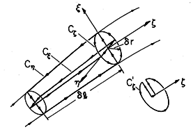
The component of the curl in the  direction is the limit in
which the area 2
 r
r l goes to zero of the circulation
around the contour C
 divided by that area. The contributions to
this line integration from the segments that are perpendicular to the
 axis are by definition zero. Thus, for this component of the
curl, transverse to the field, (2.4.2) becomes

The transverse components of the curl can be regarded as derivatives
with respect to transverse directions of the vector field weighted by
incremental line elements  l.
l.
At its center, the surface enclosed by the contour C has its
normal in the direction of the field. It would seem that the curl in
the
  direction would therefore have to be zero. However, the
previous discussion and illustration give a warning that the contour
integral around C
 is not necessarily zero.
Even though, to zero order in the diameter of the hose, the field
is perpendicular to the contour, to higher order it can have
components parallel to the contour. This means that if the contour
C were actually perpendicular to the field at each point,
it would not close on itself. An equivalent contour, shown by the
inset to Fig. 2.7.6, begins and terminates on the central field line.
With the exception of the segment in the
  direction used to close
this contour, each segment is now by definition perpendicular to
 .
The contribution to the circulation around the contour now comes from
the
  -directed segment. Remember that the length of this segment is
determined by the shape of the field lines. Thus, it is proportional
to (
 r)2, and therefore so also is the circulation. The
limit defined
by (2.1.2) can result in a finite value in the
  direction. The
"cross-product" of an operator with a vector has properties that are
not identical with the cross-product of two vectors.


