To set the stage for the next two sections, consider the fields in a material that has a linear polarizability and is described by Ohm's law, (7.1.7).

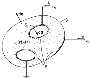
In general, these properties are functions of position, r. Typically, electrodes are used to constrain the potential over some of the surface enclosing this material, as suggested by Fig. 7.2.1.
In this section, we suppose that the excitations are essentially constant in time, in the sense that the rate of accumulation of charge at any given location has a negligible influence on the distribution of the current density. Thus, the time derivative of the unpaired charge density in the charge conservation law, (7.0.3), is negligible. This implies that the current density is solenoidal.

Of course, in the EQS approximation, the electric field is also irrotational.

Combining (2) and (3) gives a second-order differential equation for the potential distribution.

In regions of uniform conductivity ( = constant), it assumes
a familiar form.

In a uniform conductor, the potential distribution satisfies Laplace's equation.
It is important to realize that the physical reasons for obtaining Laplace's equation for the potential distribution in a uniform conductor are quite different from those that led to Laplace's equation in the electroquasistatic cases of Chaps. 4 and 5. With steady conduction, the governing requirement is that the divergence of the current density vanish. The unpaired charge density does not influence the current distribution, but is rather determined by it. In a uniform conductor, the continuity constraint on J happens to imply that there is no unpaired charge density.
In a nonuniform conductor, (4) shows that there is an
accumulation of unpaired charge. Indeed, with  a function of
position, (2) becomes

Once the potential distribution has been found, Gauss' law can be used to determine the distribution of unpaired charge density.

Equation (6) can be solved for div E and that quantity substituted into (7) to obtain

Even though the distribution of  plays no part in determining
E, through Gauss' law, it does influence the distribution of
unpaired charge density.
Continuity Conditions
Where the conductivity changes abruptly, the continuity conditions follow from (2) and (3). The condition

is derived from (2), just as (1.3.17) followed from Gauss' law. The continuity conditions implied by (3) are familiar from Sec. 5.3.

Illustration. Boundary Condition at an Insulating Surface
Insulated wires and ordinary resistors are examples where a conducting medium is bounded by one that is essentially insulating. What boundary condition should be used to determine the current distribution inside the conducting material?
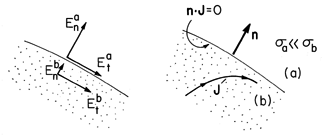
Figure 7.2.2 Boundary between region (a) that is insulating relative to region (b). In Fig. 7.2.2, region (a) is relatively insulating compared to region (b),
a

b. It follows from (9) that the normal electric field in region (a) is much greater than in region (b), Ena
Enb. According to (10), the tangential components of E are equal, Eta = Etb. With the assumption that the normal and tangential components of E are of the same order of magnitude in the insulating region, these two statements establish the relative magnitudes of the normal and tangential components of E, respectively, sketched in Fig. 7.2.2. We conclude that in the relatively conducting region (b), the normal component of E is essentially zero compared to the tangential component. Thus, to determine the fields in the relatively conducting region, the boundary condition used at an insulating surface is
At an insulating boundary, inside the conductor, the normal derivative of the potential is zero, while the boundary potential adjusts itself to make this true. Current lines are diverted so that they remain tangential to the insulating boundary, as sketched in Fig. 7.2.2.
Just as Gauss' law embodied in (8) is used to find the unpaired volume charge density ex post facto, Gauss' continuity condition (6.5.3) serves to evaluate the unpaired surface charge density. Combined with the current continuity condition, (9), it becomes

Conductance
If there are only two electrodes contacting the conductor of Fig. 7.2.1 and hence one voltage v1 = v and current i1 = i, the voltage-current relation for the terminal pair is of the form

where G is the conductance. To relate G to field quantities, (2) is
integrated over a volume V enclosed by a surface S, and Gauss' theorem
is used to convert the volume integral to one of the current  E
E  da over
the surface S. This integral law is then applied to the surface shown
in Fig. 7.2.1 enclosing the electrode that is connected to the
positive terminal. Where it intersects the wire, the contribution is
-i, so that the integral over the closed surface becomes

where S1 is the surface where the perfectly conducting electrode having potential v1 interfaces with the Ohmic conductor.
Division of (14) by the terminal voltage v gives an expression for the conductance defined by (13).

Note that the linearity of the equation governing the potential distribution, (4), assures that i is proportional to v. Hence, (15) is independent of v and, indeed, a parameter characterizing the system independent of the excitation.
A comparison of (15) for the conductance with (6.5.6) for the capacitance suggests an analogy that will be developed in Sec. 7.5.
Qualitative View of Fields in Conductors
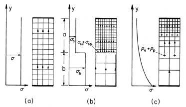
Three classes of steady conduction configurations are typified in Fig. 7.2.3. In the first, the region of interest is one of uniform conductivity bounded either by surfaces with constrained potentials or by perfect insulators. In the second, the conductivity varies abruptly but by a finite amount at interfaces, while in the third, it varies smoothly. Because Gauss' law plays no role in determining the potential distribution, the permittivity distributions in these three classes of configurations are arbitrary. Of course, they do have a strong influence on the resulting distributions of unpaired charge density.
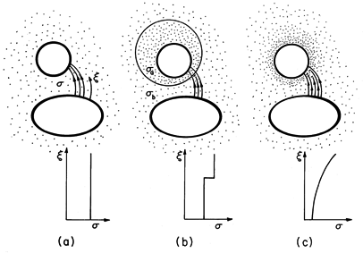
A qualitative picture of the electric field distribution within
conductors emerges from arguments similar to those used in Sec. 6.5
for linear dielectrics. Because J is solenoidal and has the same
direction as E, it passes from the high-potential to the
low-potential electrodes through tubes within which lines of J
neither terminate nor originate. The
E lines form the same tubes but either terminate or originate on
the sum of unpaired and polarization charges. The sum of these charge
densities is div  o E, which can be
determined from (6).

At an abrupt discontinuity, the sum of the surface charges determines the discontinuity of normal E. In view of (9),

Note that the distribution of  plays no part in shaping the
E lines.
In following a typical current tube from high potential to low in
the uniform conductor of Fig. 7.2.3a, no conductivity gradients are
encountered, so (16) tells us there is no source of E. Thus,
it is no surprise that  satisfies Laplace's equation throughout
the uniform conductor.
In following the current tube through the discontinuity of Fig. 7.2.3b, from low to high conductivity, (17) shows that there is a negative surface source of E. Thus, E tends to be excluded from the more conducting region and intensified in the less conducting region.
With the conductivity increasing smoothly in the direction of
E, as illustrated in Fig. 7.2.3c, E 

 is
positive. Thus, the source of E is negative and the E
lines attenuate along the flux tube.
Uniform and piece-wise uniform conductors are commonly encountered, and examples in this category are taken up in Secs. 7.4 and 7.5. Examples where the conductivity is smoothly distributed are analogous to the smoothly varying permittivity configurations exemplified in Sec. 6.7. In a simple one-dimensional configuration, the following example illustrates all three categories.
Example 7.2.1. One-Dimensional Resistors
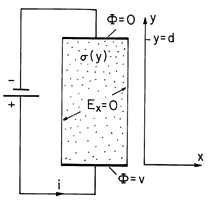
The resistor shown in Fig. 7.2.4 has a uniform cross-section of area A in any x - z plane. Over its length d it has a conductivity
(y). Perfectly conducting electrodes constrain the potential to be v at y = 0 and to be zero at y = d. The cylindrical conductor is surrounded by a perfect insulator.
Figure 7.2.4 Cylindrical resistor having conductivity that is a function of position y between the electrodes. The material surrounding the conductor is insulating. The potential is assumed to depend only on y. Thus, the electric field and current density are y directed, and the condition that there be no component of E normal to the insulating boundaries is automatically satisfied. For the one-dimensional field, (4) reduces to
The quantity in parentheses, the negative of the current density, is conserved over the length of the resistor. Thus, with Jo defined as constant,
This expression is now integrated from the lower electrode to an arbitrary location y.
Evaluation of this expression where y = d and
= 0 relates the current density to the terminal voltage.
Introduction of this expression into (20) then gives the potential distribution.
The conductance, defined by (15), follows from (21).
These relations hold for any one-dimensional distribution of
. Of course, there is no dependence on
, which could have any distribution. The permittivity could even depend on x and z. In terms of the circuit analogy suggested in the introduction, the resistors determine the distribution of voltages regardless of the interconnected capacitors.
Three special cases conform to the three categories of configurations illustrated in Fig. 7.2.3.
Uniform Conductivity
If
is uniform, evaluation of (22) and (23) gives
The potential and electric field are the same as they would be between plane parallel electrodes in free space in a uniform perfect dielectric. However, because of the insulating walls, the conduction field remains uniform regardless of the length of the resistor compared to its transverse dimensions.
It is clear from (16) that there is no volume charge density, and this is consistent with the uniform field that has been found. These distributions of
,
, and E are shown in Fig. 7.2.5a.
Figure 7.2.5 Conductivity, potential, charge density, and field distributions in special cases for the configuration of Fig. 7.2.4. (a) Uniform conductivity. (b) Layers of uniform but different conductivities. (c) Exponentially varying conductivity.
Piece-Wise Uniform Conductivity
With the resistor composed of uniformly conducting layers in series, as shown in Fig. 7.2.5b, the potential and conductance follow from (22) and (23) as
Again, there are no sources to distort the electric field in the uniformly conducting regions. However, at the discontinuity in conductivity, (17) shows that there is surface charge. For
b >
a, this surface charge is positive, tending to account for the more intense field shown in Fig. 7.2.5b in the upper region.
Smoothly Varying Conductivity
With the exponential variation
=
o exp (-y/d), (22) and (23) become
Here the charge density that accounts for the distribution of E follows from (16).
Thus, the field is shielded from the lower region by an exponentially increasing volume charge density.


