Under steady conditions, conservation of charge requires that the current density be solenoidal. Thus, J lines do not originate or terminate. We have so far thought of current tubes as originating outside the region of interest, on the boundaries. It is sometimes convenient to introduce a volume distribution of current sources, s(r, t) A/m3, defined so that the steady charge conservation equation becomes
The motivation for introducing a distributed source of current becomes clear as we now define singular sources and think about how these can be realized physically.
Distributed Current Source Singularities
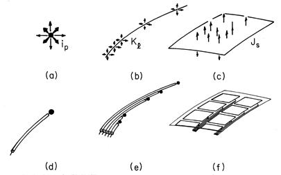
The analogy between (1) and Gauss' law begs for the definition of point, line, and surface current sources, as depicted in Fig. 7.3.1. In returning to Sec. 1.3 where the analogous singular charge distributions were defined, it should be kept in mind that we are now considering a source of current density, not of electric flux.
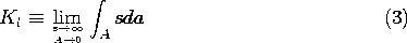
Figure 7.3.1 Singular current source distributions represented conceptually by the top row, suggesting how these might be realized physically by the bottom row by electrodes fed through insulated wires. A point source of current gives rise to a net current ip out of a volume V that shrinks to zero while always enveloping the source.
Such a source might be used to represent the current distribution around a small electrode introduced into a conducting material. As shown in Fig. 7.3.1d, the electrode is connected to a source of current ip through an insulated wire. At least under steady conditions, the wire and its insulation can be made fine enough so that the current distribution in the surrounding conductor is not disturbed.
Note that if the wire and its insulation are considered, the current density remains solenoidal. A surface surrounding the spherical electrode is pierced by the wire. The contribution to the integral of J
da from this part of the surface integral is equal and opposite to that of the remainder of the surface surrounding the electrode. The point source is, in this case, an artifice for ignoring the effect of the insulated wire on the current distribution.
The tubular volume having a cross-sectional area A used to define a line charge density in Sec. 1.3 (Fig. 1.3.4) is equally applicable here to defining a line current density.
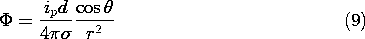
In general, Kl is a function of position along the line, as shown in Fig. 7.3.1b. If this is the case, a physical realization would require a bundle of insulated wires, each terminated in an electrode segment delivering its current to the surrounding medium, as shown in Fig. 7.3.1e. Most often, the line source is used with two-dimensional flows and describes a uniform wire electrode driven at one end by a current source.
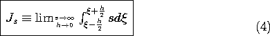
The surface current source of Figs. 7.3.1c and 7.3.1f is defined using the same incremental control volume enclosing the surface source as shown in Fig. 1.3.5.
Note that Js is the net current density entering the surrounding material at a given location.
Fields Associated with Current Source Singularities
In the immediate vicinity of a point current source immersed in a uniform conductor, the current distribution is spherically symmetric. Thus, with J =
E, the integral current continuity law, (1), requires that
From this, the electric field intensity and potential of a point source follow as
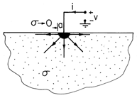
Example 7.3.1. Conductance of an Isolated Spherical Electrode
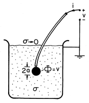
A simple way to measure the conductivity of a liquid is based on using a small spherical electrode of radius a, as shown in Fig. 7.3.2. The electrode, connected to an insulated wire, is immersed in the liquid of uniform conductivity
Figure 7.3.2 For a small spherical electrode, the conductance relative to a large conductor at "infinity" is given by (7). By definition the potential at the surface of the sphere is v, so evaluation of the potential for a point source, (6), at r = a gives
This conductance is analogous to the capacitance of an isolated spherical electrode, as given by (4.6.8). Here, a fine insulated wire connected to the sphere would have little effect on the current distribution.
The conductance associated with a contact on a conducting material is often approximated by picturing the contact as a hemispherical electrode, as shown in Fig. 7.3.3. The region above the surface is an insulator. Thus, there is no current density and hence no electric field intensity normal to this surface. Note that this condition is satisfied by the field associated with a point source positioned on the conductor-insulator interface. An additional requirement is that the potential on the surface of the electrode be v. Because current is carried by only half of the spherical surface, it follows from reevaluation of (6a) that the conductance of the hemispherical surface contact is
Figure 7.3.3 Hemispherical electrode provides contact with infinite half-space of material with conductance given by (8).
The fields associated with uniform line and surface sources are analogous to those discussed for line and surface charges in Sec. 1.3.
The superposition principle, as discussed for Poisson's equation in Sec. 4.3, is equally applicable here. Thus, the fields associated with higher-order source singularities can again be found by superimposing those of the basic singular sources already defined. Because it can be used to model a battery imbedded in a conductor, the dipole source is of particular importance.
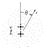
Example 7.3.2. Dipole Current Source in Spherical Coordinates
A positive point current source of magnitude ip is located at z = d, just above a negative source (a sink) of equal magnitude at the origin. The source-sink pair, shown in Fig. 7.3.4, gives rise to fields analogous to those of Fig. 4.4.2. In the limit where the spacing d goes to zero while the product of the source strength and this spacing remains finite, this pair of sources forms a dipole. Starting with the potential as given for a source at the origin by (6), the limiting process is the same as leading to (4.4.8). The charge dipole moment qd is replaced by the current dipole moment ip d and
o

Figure 7.3.4 Three-dimensional dipole current source has potential given by (9). The potential of a polar dipole current source is found in Prob. 7.3.3.
Method of Images
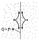
With the new boundary conditions describing steady current distributions come additional opportunities to exploit symmetry, as discussed in Sec. 4.7. Figure 7.3.5 shows a pair of equal magnitude point current sources located at equal distances to the right and left of a planar surface. By contrast with the point charges of Fig. 4.7.1, these sources are of the same sign. Thus, the electric field normal to the surface is zero rather than the tangential field. The field and current distribution in the right half is the same as if that region were filled by a uniform conductor and bounded by an insulator on its left.
Figure 7.3.5 Point current source and its image representing an insulating boundary.