A general solution to (8.0.2) is

where A is the vector potential. Just as E = -grad
 is the "integral" of the EQS equation curl E = 0,
so too is (1) the "integral" of (8.0.2).
Remember that we could add an arbitrary constant to
  without
affecting E. In the case of the vector potential, we can add the
gradient of an arbitrary scalar function to A without affecting
H. Indeed, because
  x (\nabla
 ) = 0,
we can replace A by A' = A +
 .
The curl of A is the same as of A'.
We can interpret (1) as the specification of A in terms of the assumedly known physical H field. But as pointed out in the introduction, to uniquely specify a vector field, both its curl and divergence must be given. In order to specify A uniquely, we must also give its divergence. Just what we specify here is a matter of convenience and will vary in accordance with the application. In MQS systems, we shall find it convenient to make the vector potential solenoidal

Specification of the potential in this way is sometimes called setting the gauge, and with (2) we have established the Coulomb gauge.
We turn now to the evaluation of A, and hence H, from the MQS Ampère's law and magnetic flux continuity law, (8.0.1) and (8.0.2). The latter is automatically satisfied by letting the magnetic flux density be represented in terms of the vector potential, (1). Substituting (1) into Ampère's law (8.0.1) then gives

The following identity holds.

The reason for defining A as solenoidal was to eliminate the

 A term in this expression and to reduce (3) to
the vector Poisson's equation.

The vector Laplacian on the left in this expression is defined in Cartesian coordinates as having components that are the scalar Laplacian operating on the respective components of A. Thus, (5) is equivalent to three scalar Poisson's equations, one for each Cartesian component of the vector equation. For example, the z component is

With the identification of Az 
 and
and  o Jz
o Jz

 /
/ o, this expression becomes the
scalar Poisson's equation of Chap. 4, (4.2.2). The integral of this
latter equation is the superposition integral, (4.5.3). Thus,
identification of variables gives as the integral of (6)

and two similar equations for the other two components of A. Reconstructing the vector A by multiplying (7) by iz and adding the corresponding x and y components, we obtain the superposition integral for the vector potential.

Remember, r' is the coordinate of the current density source, while
r is the coordinate of the point at which A is evaluated, the
observer coordinate.
Given the current density everywhere, this integration provides the
vector potential. Hence, in principle, the flux density  o H
is determined by carrying out the integration and then
taking the curl in accordance with (1).
The theorem at the end of Sec. 8.0 makes it clear that the solution provided by (8) is indeed unique when the current density is given everywhere.
In order that  x A be a physical flux density,
J (r) cannot be an arbitrary vector field. Because div
(curl) of any vector is identically equal to zero, the divergence of
the quasistatic Ampère's law, (8.0.1), gives
 (
( x H) = 0 = \nabla
  J and thus

The current distributions of magnetoquasistatics must be solenoidal.
Of course, we know from the discussion of uniqueness given in Sec. 8.0 that (9) does not uniquely specify the current distribution. In an Ohmic conductor, stationary current distributions satisfying (9) were determined in Secs. 7.1-7.5. Thus, any of these distributions can be used in (8). Even under dynamic conditions, (9) remains valid for MQS systems. However, in Secs. 8.4-8.6 and as will be discussed in detail in Chap. 10, if time rates of change become too rapid, Faraday's law demands a rotational electric field which plays a role in determining the distribution of current density. For now, we assume that the current distribution is that for steady Ohmic conduction.
\sectnonumTwo-Dimensional Current and Vector Potential Distributions
Suppose a current distribution J = iz Jz(x, y) exists through all of space. Then the vector potential is z directed, according to (8), and its z component obeys the scalar Poisson equation

But this is formally the same expression, (4.5.3), as that of the
scalar potential produced by a charge distribution  (x' ,
y' ).

It was inconvenient to integrate the above equation directly. Instead, we determined the field of a line charge from symmetry and Gauss' law and integrated the resulting expression to obtain the potential (4.5.18)

where r is the distance from the line charge r =  (x -
x' )2 + (y - y' )2 and ro is the reference radius.
The scalar potential can thus be evaluated from the two-dimensional
integral

The vector potential of a two-dimensional z-directed current distribution obeys the same equation and thus has a solution by analogy, after a proper interchange of parameters.

Two important consequences emerge from this derivation.
by a given charge distribution  (x, y), has an MQS analog vector
potential Az(x, y) caused by a current density Jz(x, y) with
the same spatial distribution as
  (x, y). The magnetic field
follows from (1) and thus

Therefore the lines of magnetic flux density are perpendicular to the gradient of Az. A plot of field lines and equipotential lines of the EQS problem is transformed into a plot of an MQS field problem by interpreting the equipotential lines as the lines of magnetic flux density. Lines of constant Az are lines of magnetic flux.
| (a) | Every two-dimensional EQS potential  (x, y) produced (x, y) produced
|
| (b) | The vector potential of a line current of magnitude i
along the z direction is given by analogy with (12),

which is consistent with the magnetic field H = i

|
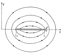
Example 8.1.1. Field Associated with a Current Sheet
A z-directed current density is uniformly distributed over a strip located between x2 and x1 as shown in Fig. 8.1.1. The thickness of the sheet,
, is very small compared to other dimensions of interest. So, the integration of (14) in the y direction amounts to a multiplication of the current density by
. The vector potential is therefore determined by completing the integration on x'
where Ko \equiv Jz
.
Figure 8.1.1 Cross-section of surfaces of constant Az and lines of magnetic flux density for the uniform sheet of current shown. This integral is carried out in Example 4.5.3, where the two dimensional electric potential of a charged strip was determined. Thus, with
o /
o

o Ko, (4.5.24) becomes the desired vector potential.
The profiles of surfaces of constant Az are shown in Fig. 8.1.1. Remember, these are also the lines of magnetic flux density,
o H.
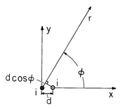
Example 8.1.2. Two-Dimensional Magnetic Dipole Field
A pair of closely spaced conductors carrying oppositely directed currents of magnitude i is shown in Fig. 8.1.2. The currents extend to + and - infinity in the z direction, so the resulting fields are two-dimensional and can be represented by Az. In polar coordinates, the distance from the right conductor, which is at a distance d from the z axis, to the observer location is essentially r - d cos
. The Az for each wire takes the form of (16), with r the distance from the wire to the point of observation. Thus, superposition of the vector potentials due to the two wires gives
In the limit d \ll r, this expression becomes
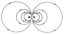
Thus, the surfaces of constant Az have intersections with planes of constant z that are circular, as shown in Fig. 8.1.3. These are also the lines of magnetic flux density, which follow from (17).
Figure 8.1.2 A pair of wires having the spacing d carry the current i in opposite directions parallel to the z axis. The two-dimensional dipole field is shown in Fig. 8.1.3.
Figure 8.1.3 Cross-sections of surfaces of constant Az and hence lines of magnetic flux density for configuration of Fig. 8.1.2. If the line currents are replaced by line charges, the resulting equipotential lines (intersections of the equipotential surfaces with the x - y plane) coincide with the magnetic field lines shown in Fig. 8.1.3. Thus, the lines of electric field intensity for the electric dual of the magnetic configuration shown in Fig. 8.1.3 originate on the positive line charge on the right and terminate on the negative line charge at the left, following lines that are perpendicular to those shown.


 r) given by (1.4.10), if one makes use of the curl
expression in polar coordinates,


