In a typical physical situation to which the scalar potential is
applicable, layers of wire are used to make a winding that is thin
compared to other dimensions of interest. Currents are then confined
to surfaces that separate the regions where H is irrotational.
Thus, the sources of the magnetic field intensity can be represented
as surface currents. The field produced by these currents is then
found by choosing source-free solutions in the space surrounding the
current-carrying surfaces and "connecting" these solutions across
the surfaces by the proper boundary conditions. This procedure is
analogous to finding EQS potentials produced by
charge sheets in Chap. 5. Solutions to Laplace's equation were set
up on the two sides of a charge sheet and the jump in normal
 oE adjusted to equal the surface charge density.
In the MQS situation, the H field obeys Ampère's continuity condition, (1.4.16).

At this same surface, the magnetic flux continuity condition, (1.7.6), also applies.

Remember that in Chap. 5, continuity of tangential E was implied
by making the electric potential continuous. By contrast, according to
(1), where there is a surface current density, the tangential H
is discontinuous and this implies that the magnetic scalar potential
 is not generally continuous. To see this, consider the
application of Ampère's integral law to an incremental surface that
is pierced by the surface current density, as shown in Fig. 8.5.1. If
H is finite, then in the limit where the width w goes to zero,
the contributions to the line integral from the segments B
 B' and A'
  A vanish, and so

where the unit vectors is and in are defined in Fig. 8.5.1.
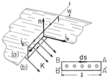
Multiplication of (3) by the incremental line element ds and integration over the length of the incremental surface gives

In view of the gradient integral theorem, (4.1.16), the integrals on the left can be carried out to obtain

Now think of A - A' as a fixed reference position on the
surface, where  A is defined as being equal to
 A'. It then follows
that the discontinuity in
  at the location B - B' is a
measure of the net current passing normal to the strip joining A -
A' to B - B'.
A further contrast with the electric field comes from the normal
field continuity condition, (2). At a surface carrying a surface
current density in free space, the normal derivative of  is
continuous.
The following example shows how to find  , and hence H, when
a surface current distribution is given.
Example 8.5.1. The Spherical Coil
The magnetic field intensity produced inside a properly wound spherical coil has the important property that it is uniform. This should be contrasted with the field of a long solenoid that is uniform only to the extent that the fringing field can be neglected.
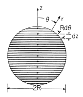
The coil is wound of thin wire so that the turns density is sinusoidally distributed between the north and south poles of a sphere. To the extent that we can disregard the slight pitch in the coil needed to connect the loops with each other, loops of appropriately varying diameter, spaced evenly as projected onto the z axis, automatically simulate such a distribution. The coil, with a radius R and a wire carrying the current i, is shown in Fig. 8.5.2.
Figure 8.5.2 Cross-section of "flux ball" consisting of sphere with winding on its surface that is of uniform turns density with respect to the z axis. To deduce the surface current density representing this winding, note that the density of turns on the surface is the total number, N, divided by the total length, 2R, and so the number of turns in the incremental length dz is (N/2R)dz. Because z = r cos
, a differential length dz corresponds to an angular increment d
: dz = - sin
R d
. Therefore, the number of turns in the differential length Rd
as measured along the periphery of the sphere is (N/2R) sin
. With each turn carrying the current i, the surface current density is
In the spaces interior and exterior to the surface of the sphere, H is both irrotational and solenoidal. Hence, it is represented by scalar magnetic potentials.
The
component of (1) is the link between the surface current density and the induced field.
To obtain H
, the derivative of
with respect to
must be taken, and this suggests that the
dependence of
be taken as cos
. The field is finite at the origin and zero at infinity, so, from the three solutions to Laplace's equation given in Sec. 5.9, we select
The continuity conditions, used now to determine the coefficients A and C, are in terms of the field intensity. Thus, (8) and (9) are used to write H in the two regions as
Substitution of the appropriate components into the continuity conditions, (2) and (7), gives
Thus, the magnetic field intensity of (10) and (11) is evaluated by setting C = -2A = -Ni/3.
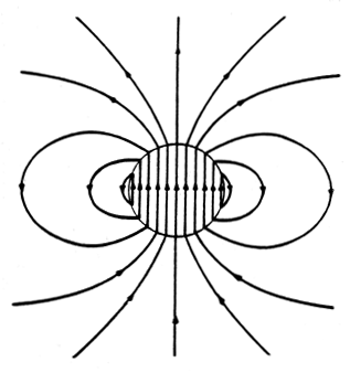
The exterior lines of magnetic field intensity are those of a dipole, while the interior field is uniform. Thus, the total picture, shown in Fig. 8.5.3, is one of field lines circulating from south to north inside the sphere and back from north to south on the outside around currents that follow lines of equilatitude around the sphere.
Figure 8.5.3 Magnetic field intensity of "flux-ball" shown in Fig. 8.5.2. The magnetic potential follows by substituting C = -2A = -Ni/3 for C and A in (8) and (9).
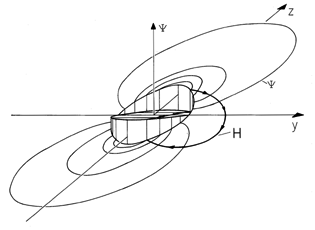
Note that these potentials are equal at the equator of the sphere and become increasingly disparate as the poles are approached. With the vertical dimension used to denote
, a sketch of
evaluated in a plane of fixed
would appear as shown in Fig. 8.5.4. Inside,
slopes linearly from its highest value at the south pole to its lowest at the north. Outside,
has its highest value at the north pole and lowest at the south. This is consistent with the picture afforded by Fig. 8.5.1 and (5). Even though it closes on itself, the line of H shown goes continuously "down hill." The potential
regains its altitude in the region of discontinuity.
Figure 8.5.4 Magnetic scalar potential for "flux ball" of Fig. 8.5.2. The vertical axis is . A line of H closes on itself as it circulates around surface current, going down the potential "hills" inside and outside the sphere and recovering its altitude at the surfaces of discontinuity at r = R, containing the surface current density.
Finally, we illustrate the computation of the inductance of a coil modeled by a surface current and represented in terms of the magnetic scalar potential. To compute the total flux linked by the winding, first consider the flux linked by one turn at the location r = R and
=
'. Using the flat surface at z' = R cos
' that is enclosed by this circular turn, the flux is
In this particular problem, Hz is uniform inside the sphere, so this integration amounts to multiplying the area enclosed by the turn by the normal flux density.
The turns density multiplied by R d
gives the number of turns linking this flux in an increment of peripheral length. Thus, the total flux is obtained by carrying out a second integration over all of the turns.
 Demonstration 8.5.1. Field and Inductance of a Spherical Coil
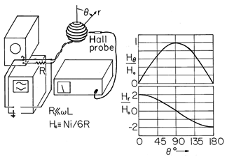
In the experiment shown in Fig. 8.5.5, the "flux ball" has 64 turns and a radius of R = 5 cm. The turns are wound on a plastic sphere that essentially has the magnetic properties of free space.
Figure 8.5.5 Demonstration of fields surrounding the magnetic "flux ball." The Hall magnetometer makes it possible to probe the magnitude and direction of the field outside the coil. For example, at the north pole, where the magnetic flux density is perpendicular to the sphere surface, the flux density is vertical and for i = 1 A predicted by either (14) or (15) to be
o Ni/3R = 5.36 x 10⁻⁴ T = 5.36 gauss. The inductance is determined by measuring the voltage and current, varying the frequency to determine that it is high enough to assure that the resistance of the coil plays a negligible role in the terminal impedance (the impedance should be of magnitude
L, and hence vary linearly with frequency). The inductance predicted by (20) is 180
H, and the value measured using the oscilloscope is typically within 10 percent.


