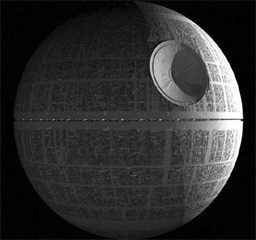
Goal: Implement a simple Pong like game with images on a monitor. In place of a puck, an image of a Death Star from Stars Wars will be used. (Death Star from F2017 Project by Nicholas Waltman/Mike Wang.)
Project files
Checkoff Part 1
Demonstrate operation of Integrated Logic Analyzer (ILA) showing the
values of the color bar (pixel) as hcount increases.
Checkoff Part 2
Please be ready with the following for this part:
Grading: Items a-d: 3 points; Items e-i: 5 points.
During checkoff you may be asked to discuss one or more of the following questions:
Video display technologies: HDMI & VGA
HDMI (High-Definition Multimedia Interface) and VGA (Video Graphics Array) are both standards for connecting a device to a monitor. Both standards define the physical interconnect and electrical characteristics of the interface. At the top level, the main difference is that VGA is analog and video only, while HDMI is digital and carries audio. [The USB-C standard that includes power, video and audio may soon replace HDMI.]
Regardless of the interface, most video displays (HDMI or VGA) create the image in a serial fashion, usually a sequence of horizontal scan lines to be displayed one under another with a small vertical offset to create a raster image. Typically the raster is transmitted in left-to-right, top-to-bottom order. A complete raster image is called a frame and one can create the appearance of motion by displaying frames in rapid succession (24 frames/sec in movies, 30 frames/sec in broadcast TV, 60+ frames/sec in computer monitors, 120 frames in high end TV).
To transmit a raster image, one must encode the color image information and provide some control signals that indicate the end of each horizontal scan line (horizontal sync) and frame (vertical sync). The display device creates the image using red, green and blue emitters, so an obvious way to encode the color information is to send separate signals that encode the appropriate intensity of red, green and blue. This is indeed how most analog computer monitors work -- they accept 5 analog signals (red, green, blue, hsync, and vsync) over a standardized HD15 connector. The signals are transmitted as 0.7V peak-to-peak (1V peak-to-peak if the signal also encodes sync). The monitor supplies a 75Ω termination for each signal, which if matched with a driver and cable with a characteristic impedance of 75Ω minimizes the interference due to signal reflections.
Unlike VGA, which is analog, HDMI is all digital and uses transition-minimized differential signaling (TMDS). With differential signaling, a pair of wires (for each signal) is used with one wire carrying the signal and the other wire carrying an inverted signal (voltage) of the signal. At the receiver, the difference between the differential pair is the resulting signal. Using differential pair results in better noise immunity. TMDS also uses an encoding method that reduces the number of transitions in the signal thus minimizing EMI. Similar to VGA, HDMI has an active video period (Video Data Period) when pixels are transmitted. Unlike VGA, during the horizontal and vertical blanking intervals (Data Island period), audio and other data are sent. From a Verilog perspective, moving the pong game from VGA to HDMI requires adding a Verilog module to take the VGA signals and create the TMDS signals.
The labkit incorporates an integrated circuit -- the ADV7125 Triple 8-bit high-speed video DAC -- which produces the correct analog signals given the proper digital inputs: three 8-bit values for R, G and B intensity, hsync, vsync, and blanking.
The Nexys4 uses a simple resistor network to create the necessary analog voltage levels. In this case three 4-bit values for R, G and B intensity, hsync, vsync. Blanking for the Nexys4 is incorporated into the RGB values.
For this lab, we will be using the VGA output with the Nexys4 board.
To create a video image for our Pong game, it's helpful to think of the image as a rectangular array of picture elements or pixels. There are several common choices for the dimensions (HxV) of the rectangle:
There two monitors on most of the lab benches. Use the small non-wide screen monitor for the lab with 1024x768 resolution.
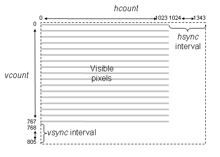
Please take a moment to read through the "VGA Video" hardware tutorial that's part of the on-line Labkit documentation. You'll see that the timings for the RGB image information relative to the horizontal and vertical syncs are somewhat complicated. For example, the horizontal sync goes active in the interval between the end of one scan line and the beginning of the next -- the exact timings are specified by the XVGA specification. Lab 3 Verilog includes an xvga module that generates the necessary signals; it uses two counters:
vcount counts scan lines in a frame. Values 0 through 767 are the 768 displayed scan lines, values 768 through 805 time interval between end of one frame and the start of the next. Specific values in this interval are decoded to time the beginning and end of the active-low vertical sync signal (vsync).
Pixel values are sent out during the active display period: (hcount < 1024 and vcount < 768).
The xvga module also generates blank, an active low signal that's 0 when a pixel value will be displayed and 1 when the pixel would be off the screen (hcount > 1023 or vcount > 767). The active low logic is a historical artifact and is in used many VGA interface chips such as the AD7125 in the old labkit.
You can use (hcount, vcount) as the (x,y) coordinate of the pixel to be displayed: (0,0) is the top-left pixel, (1023,0) is the top-right pixel, (1023,767) is the bottom-right pixel, etc. Given the coordinates and dimensions of a graphic element, your game logic can use (hcount, vcount) to determine the contribution the graphic element makes to the current pixel. If you are storing the pixels in an one dimension memory array then the index of the current pixel would be hcount[9:0] + H*vcount, where H is the number of displayed pixels in each scan line.
Images
Generally images are stored in a compressed form to save on space. Two commonly used formats are PNG (portable network graphics) and JPG (Joint Photographic Experts Group) formats. PNG is a lossless compression while JPG is a lossy compression using the discrete cosine transform. The human eye, however, generally will not be able to notice the loss in fidelity with lossy compression. Another format is BMP, an uncompressed file format. With BMP, the image is stored in a two dimensional memory (frame buffer) with coordinates ( i, j) corresponding to the i th column, j th row pixel in the image. Each pixel can be represented as single bit (black or white) or up to 24 bits for color. The image Death Star below is 256 x 240 pixels with each pixel containing 8 bits of information.
However, frame buffer memory in digital systems is generally organized as a flat one dimensional memory or a linear memory model with an index into a single contiguous address space. The conversion of the addressing from two dimensions to linear addressing is straight forward. For a given pixel of the image at location ( i, j) of the image, in our Death Star example, the index in a linear address for that pixel is i + j*256 where 256 is the width of the image.
Video output using 8 bits R,G,B requires 24 bits for each pixel. Using 24 bits is considered to be true color since any color from a palette of 16 million (2**24) can be displayed. [Note: in Verilog use "**" for exponentiation and not ^. The symbol ^ is the XOR function.]
The Nexys4 video output uses 12 bit (4 bits for R,G,B) while the older labkit uses 24 bit color.
When memory is a constrained and it generally is, a color map is used to reduce the memory usage yet still display 24 bits of color. This is accomplished by reducing the palette of 16 million colors available. In our example, using 8 bits for each pixel we can display 256 different colors. The 8 bit value is then used as an index to three color maps (for RGB) resulting in the 24 bit value sent to the VGA output. This limits the image to just 256 colors from a palette of 16 million. More on color maps later on.
Pong Game
Pong was one of the first mass-produced video games, a hit more because of its novelty than because of the gaming experience itself. Our version will be a single-player variation where the player is defending a "goal" by moving a rectangular paddle up and down the left edge of the screen. The puck (Death Star) moves about the screen with a fixed velocity, bouncing off the paddle and the implicit walls at the top, right and bottom edges of the screen. If the puck (Death Star) reaches the left edge of the screen (i.e., it wasn't stopped by bouncing off the paddle), the player looses and the game is over:
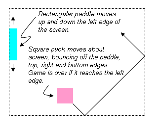
To keep the initial implementation easy, let's make the puck a 64-pixel by 64-pixel square and have it move at move diagonally at a constant velocity. We'll use switch[15:12] to set the puck's velocity in terms of pixels/frame: 4'b0000 means no motion, 4'b0101 would cause the puck (Death Star) to change both its x and y coordinate by 5 every frame (the sign of the change for each coordinate would be determined by which of the 4 possible headings the puck (Death Star) is following at the moment). When the puck (Death Star) collides with an edge or the paddle, its heading changes appropriately, e.g., a collision with the bottom edge changes the sign of the puck's y velocity.
[NB At this point, the concept and implementation in hardware of signed numbers have not been introduced. To move the puck, use a direction bit and add or subtract accordingly.]
Make the paddle 16 pixels wide and 128 pixels high. It should move up and down the left edge of the screen at 4 pixels/frame in response to the user pressing the UP or DOWN buttons on the labkit.
Pressing the ENTER (BTNC) button should reset the game to its initial state: the paddle centered on the left edge, and the puck (Death Star) somewhere in the middle of the screen, heading southeast. If the puck (Death Star) reaches the left edge, the game should stop (it can be restarted by pressing the ENTER button).
Implementation steps
Connect the VGA cable from your monitor to the VGA connector on the Nexys4.
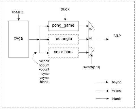
Set the slide switches so that SW[1:0] is 2'b10. You should see vertical colored bars on the monitor; the color sequence progresses through the eight possible colors where each of R, G or B is 12'hFFF or 12'h000. If don't see this image, make sure the monitor is reading from the VGA input, the cable is connected properly and the download to the FPGA completed successfully.
Now set the slide switches so that SW[1:0] is 2'b01. This should produce a one-pixel wide cross hair with a white outline around the edge of the screen. If one or more of the edges isn't visible, the image size and position can be adjusted using the monitor's controls. Push the "menu" button and use the "+" and "-" buttons to navigate to the Position and Size selections. Adjust until all four edges of the white rectangle are visible.
Finally set the slide switches so that SW[1:0] is 2'b00. You should see a
color checkerboard that is being produced by the Verilog code inside of
pong_game module. (This is the code you'll modify to implement your pong game.)
In debugging hardware, at times, it's useful to be able to view the signals. We have Tektronix Logic Analyzers in lab for that purpose. To use it, physical wires are needed and must be attached between the FPGA and the logic analyzer. And the internal signals can't be viewed! But why use an external instrument when an Integrated Logic Analyzer (ILA) core can be synthesized? With this method, no wires are needed - just Verilog. We can just route the signals of interest to the ILA. Since we are viewing real signals and not simulation, the bit stream with the synthesized design and the synthesized ILA must be loaded on to the FPGA. In this exercise, we will synthesize an ILA and view the RGB values of the pixels sent to the VGA port.
Set up the ILA to view hsync (the signal indicating the start of a scan line), hcount (the location of pixel on the line) and pixel (the value sent to the VGA port) following the instructions here.
With a working ILA you should have the following display:
The color bars are generate by every change in change hcount[5] (every 2**5 pixel)
.
Checkoff Part 1
When you get the ILA display, show to staff member for the Checkoff 1
| vclock | input | 65MHz pixel clock |
| reset | input | 1 to reset the module to its initial state, hooked to the BTNC pushbutton via a debouncing circuit |
| up | input | 1 to move paddle up, 0 otherwise. Hooked to the UP pushbutton via a debouncing circuit. |
| down | input | 1 to move paddle down, 0 otherwise. Hooked to the DOWN pushbutton via a debouncing circuit. |
| pspeed[3:0] | input | Puck (Death Star) horizontal & vertical velocity in pixels per frame. Hooked to switch[15:12] |
| hcount[10:0] | input | Counts pixels on the current scan line, generated by the xvga module. |
| vcount[9:0] | input | Counts scan lines in the current frame, generated by the xvga module. |
| hsync | input | Active-low horizontal sync signal generated by the xvga module. |
| vsync | input | Active-low vertical sync signal generated by the xvga module. |
| blank | input | Active-high blanking signal generated by the xga module. |
| phsync | output | Active-low horizontal sync signal generated by your Pong game. Often this is just hsync, perhaps delayed by a vclock if your pixel generating circuitry takes an additional vclock. |
| pvsync | output | Active-low horizontal sync signal generated by your Pong game. Often this is just vsync, perhaps delayed by a vclock if your pixel generating circuitry takes an additional vclock. |
| pblank | output | Active-high blanking signal generated by your Pong game. Often this is just blank, perhaps delayed by a vclock if your pixel generating circuitry takes an additional vclock. |
| pixel[11:0] | output | The {R,G,B} value for the current pixel, four bits for each color. |
The Death Star image contains 61440 entries (one for each pixel in the image), each entry 8 bits wide. (The image COE file, a text file with the Death Star image, actually contains 61,442 lines: 256 * 240 = 61440 + 2 lines for the header.) By using this file to initialize a ROM, the pixel's X and Y coordinates can be used to calculate the address in the ROM corresponds to that pixel. The content of the address is an 8 bit value that will be used in the next step.
The 8 bit value output from the image rom is then used as an input into another ROM initialized with Death Star color map. This file is 256 lines long (minus the two header lines) and contains the 256 most-used colors in the image generated using a MATLAB script (saving you from using the MATLAB file yourself). The 8 bit value from the first ROM is used to determine which of these 256 colors the pixel should be.
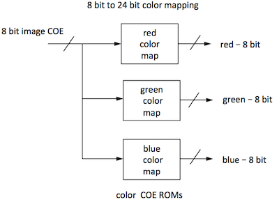
Since the image is in black and white, this 8 bit color can be used as the R, G, and B component to get a 24 bit black and white or greyscale color. Because the Nexys4 video is 12 bits, we will use the MSB 4 bits from the Death Star color map for RGB.
In short, the MATLAB script was used to come up with the 256 most used colors in the image. The results are stored in Death Star color map. You can think of the ROM initialized with Death Star color map as a list of colors used in the image. The Death Star image then tells you which of those 256 colors each pixel is. We have already created the COE files for the lab: [Death Star image COE], [Death Star color map COE]. (Here are instructions for creating your own COE files in the MATLAB script in case you wish to use your own image.)
As an example, let's calculate the color of pixel 0, the first pixel in the image. The pixel's coordinates (0,0) tells us to look at the entry at the 0th index in the Death Star image ROM, where you see the value is 0000 0111, which is 7 in decimal. The 7th entry of Death Star color map ROM is 0000 0000, so the R, G, and B values of pixel 0 are all 0000 0000 or black.
The image COE file is the pixels of the image. The color COE files are the color maps. Use these files for the initialization of the ROMs. For simplicity, use the same color map COE file for all the colors thus creating a greyscale image. You can experiment and create images of other colors by varying the ratio of R,G,B.
The generation of the ROMs also results in generated .veo files
in the source folder. The contents of the .veo files list the ports
names of the ROMs.
Here is an example of the contents:
// The following must be inserted into your Verilog file for this
// core to be instantiated. Change the instance name and port connections
// (in parentheses) to your own signal names.

//----------- Begin Cut here for INSTANTIATION Template ---// INST_TAG
image_rom YourInstanceName (
	.clka(clka),
	.addra(addra), // Bus [15 : 0]
	.douta(douta)); // Bus [7 : 0]

// INST_TAG_END ------ End INSTANTIATION Template ---------
Using the ROMs, send the appropriate pixel based on hcount, vcount.
[(R,G,B) result] = [(R,G,B) puck ] * α + [(R,G,B) object] * (1- α)
Obviously, α = 0 gives you a completely transparent puck (Death Star), while α = 1 gives you an opaque puck (Death Star). Note that each individual color needs to be multiply by alpha - not the entire 12 bit value.
R(blended) = R(puck)* α + R(object) * (1- α) G(blended) = G(puck)* α + G(object) * (1- α) B(blended) = B(puck)* α + B(object) * (1- α)
Alpha blending is a mathematical operation. Since Verilog has built in multipliers but no dividers (dividers can be created), we must implement alpha blending by multiplying and right shifting (dividing by powers of 2). Express α as m/n where m,n are integers of your choice and n is a power of 2. (1-α) must be expressed as a fraction.
Implementation Tips
You may find it useful to use the following parameterized module in your implementation of Pong. Given the pixel coordinate (hcount,vcount) it returns a non-black pixel if the coordinate falls with the appropriate rectangular area. The coordinate of the top-left corner of the rectangle is given by the x and y inputs; the width and height of the rectangle, as well as its color, are determined by module's parameters.
//////////////////////////////////////////////////////////////////////
//
// blob: generate rectangle on screen
//
//////////////////////////////////////////////////////////////////////
module blob
   #(parameter WIDTH = 64,            // default width: 64 pixels
               HEIGHT = 64,           // default height: 64 pixels
               COLOR = 12'hFFF)  // default color: white
   (input [10:0] x_in,hcount_in,
    input [9:0] y_in,vcount_in,
    output logic [11:0] pixel_out);

   always_comb begin
      if ((hcount_in >= x_in && hcount_in < (x_in+WIDTH)) &&
	 (vcount_in >= y_in && vcount_in < (y_in+HEIGHT)))
	pixel_out = COLOR;
      else pixel_out = 0;
   end
endmodule
You can instantiate several instances of blob to create different rectangles on the screen, using #(.param(value),...) to specify the instance's parameters:
logic [9:0] paddle_y;
wire [11:0] paddle_pixel;
blob #(.WIDTH(16),.HEIGHT(128),.COLOR(12'hFF0))   // yellow!
     paddle1(.x_in(11'd0),.y_in(paddle_y),.hcount_in(hcount),.vcount_in(vcount),
             .pixel_out(paddle_pixel));
[From the "more than you wanted to know" department:] blob is a very simple example of what game hardware hackers call a sprite: a piece of hardware that generates a pixel-by-pixel image of a game object. A sprite pipeline connects the output (pixel & sync signals) of one sprite to the input of the next. A sprite passes along the incoming pixel if the object the sprite represents is transparent at the current coordinate, otherwise it generates the appropriate pixel of its own. The generated pixel might come from a small image map and/or depend in some way on the sprite's internal state. Images produced by sprites later in the pipeline appear in front of sprites earlier in the pipeline, giving a pseudo 3D look to the same. This becomes even more realistic if sprites scale the image they produce so that it gets smaller if the object is supposed to be further away. The order of the pipeline becomes unimportant if a "Z" or depth value is passed along the pipeline with each pixel. The current sprite only replaces the incoming pixel/Z-value if its Z-value puts it in front of the Z-value for the incoming pixel. Simple, but sprites produced surprisingly playable games in the era before the invention of 3D graphic pipelines that can render billions of shaded triangles per second.]
Here is a modification of the blob module used to display an image. For simplicity, we use just one color map and displayed a greyscale image.
////////////////////////////////////////////////////
//
// picture_blob: display a picture
//
//////////////////////////////////////////////////
module picture_blob
   #(parameter WIDTH = 256,     // default picture width
               HEIGHT = 240)    // default picture height
   (input pixel_clk_in,
    input [10:0] x_in,hcount_in,
    input [9:0] y_in,vcount_in,
    output logic [11:0] pixel_out);

   logic [15:0] image_addr;   // num of bits for 256*240 ROM
   logic [7:0] image_bits, red_mapped, green_mapped, blue_mapped;

   // calculate rom address and read the location
   assign image_addr = (hcount_in-x_in) + (vcount_in-y_in) * WIDTH;
   image_rom  rom1(.clka(pixel_clk_in), .addra(image_addr), .douta(image_bits));

   // use color map to create 4 bits R, 4 bits G, 4 bits B
   // since the image is greyscale, just replicate the red pixels
   // and not bother with the other two color maps.
   red_coe rcm (.clka(pixel_clk_in), .addra(image_bits), .douta(red_mapped));
   //green_coe gcm (.clka(pixel_clk_in), .addra(image_bits), .douta(green_mapped));
   //blue_coe bcm (.clka(pixel_clk_in), .addra(image_bits), .douta(blue_mapped));
   // note the one clock cycle delay in pixel!
   always @ (posedge pixel_clk) begin
     if ((hcount_in >= x && hcount_in < (x_in+WIDTH)) &&
          (vcount_in >= y_in && vcount_in < (y_in+HEIGHT)))
        // use MSB 4 bits
        pixel_out <= {red_mapped[7:4], red_mapped[7:4], red_mapped[7:4]}; // greyscale
        //pixel_out <= {red_mapped[7:4], 8h'0}; // only red hues
        else pixel_out <= 0;
   end
endmodule
When encoding a color video image for broadcast or storage, it's important to use the bandwidth/bits as efficiently as possible. And, in the case of broadcast, there was the issue of backwards compatibility with black-and-white transmissions. Since the human eye has less resolution for color than intensity, the color image signal is separated into luminance (Y, essentially the old black-and-white signal) and chrominance (U/Cr/Pr, V/Cb/Pb). YUV are related to RGB as follows:
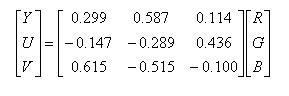
Luminance and chrominance are encoded separately and transmitted/stored at different bandwidths. In most systems the chrominance bandwidth is a half (4:2:2 format) or a quarter (4:2:0 format) of the luminance bandwidth. There are several common ways of transmitting Y, U and V:
Some transmission schemes break a frame into an even field (containing the even numbered scan lines) and an odd field (containing the odd numbered scan lines) and then transmit the fields in alternation. This technique is called interlacing and permits slower frame rates (and hence lower bandwidths) while still avoiding the problem of image flicker. When higher bandwidths are available, non-interlaced transmissions are preferred (often called progressive scan).
The labkit in the older FPGA contains interface chips for encoding (ADV7194) and decoding (ADV7185) composite and S-Video signals. The decoder chip is particularly useful if you want to use a video camera signal as part of your project.