|
|
|

for 6.111 Introduction to Digital Systems
6.111 home → Labkit home → Simulating with ModelSim
Simulating with ModelSim
by Nathan Ickes, Daniel Finchelstein, and Nathan AckermanIntroduction
The design of complex digital systems invariably requires extensive simulation, both of the individual submodules that make up the system, and of the system as a whole. This document describes how to setup and run Verilog simulations, using Project Navigator and ModelSim.
Simulations are controlled using testbenches. A testbench is an additional Verilog module (not part of the actual system design) used to generate the appropriate waveforms on the input ports of the module under test, in order to exercise the functionality of that module. Optionally, the testbench also monitors the outputs of the module under test, and generates warnings if they deviate from the expected output values. (If the testbench does not monitor the modules output, proper operation of the module under test must be verified by manual observation of the simulated output waveforms.)
Setting up the Tutorial Project
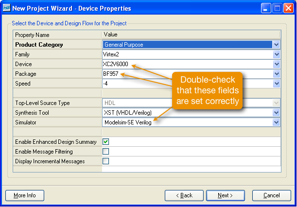
The example code for this tutorial is a very simple finite-state machine. To setup the project for this tutorial, launch Project Navigator and create a new project (targeting the labkit's XC2V6000-4BF957 FPGA). Make sure ModelSim-SE Verilog is selected as simulator in the project properties form.
Add the following source files to the project:
fsm.v: finite state machine modellabkit.v: standard labkit top-level file, modified to instantiate the above finite state machine.labkit.ucf: standard labkit constraints file.
The project source tree should look like this:
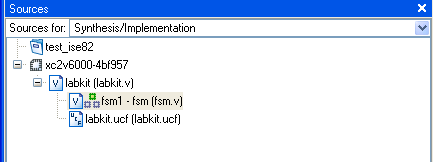
Synthesize and implement the project now, just to verify that everything is set up properly. (Don't forget to check the "Allow unmatched LOC constraints" checkbox, in the "Implement Design" properties.)
Adding a Testbench to the Project
It may be easiest to write your testbenches from scratch. However, if you wish, Project Navigator can automatically generate a skeletal testbench for any module in your design. The skeletal testbench includes code to instantiate the module under test, and to initialize the input signals to the module. You must extend the testbench in order to generate the stimulus waveforms necessary to test your module.
Select the fsm module in the project source tree. Right-click in the source-tree area and choose "New Source..." from the pop-up menu. Select "Verilog Test Fixture" from the list of source types, and choose a name for the testbench file, as shown below.
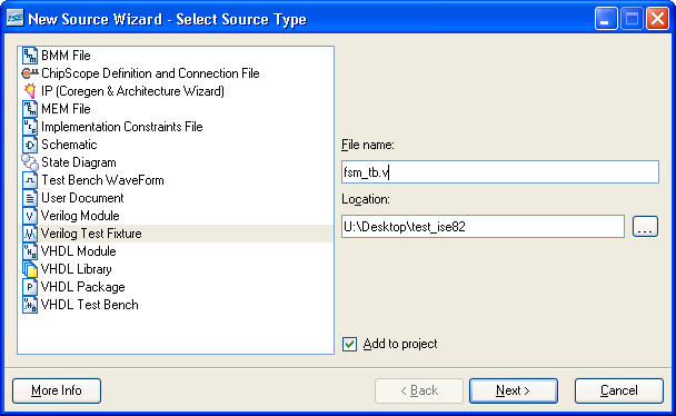
Click "Next", and then "Next" again, acknowledging fsm as the source file upon which the new testbench will be based.

Finally, click "Finish". ISE will generate a basic testbench which instantiates the fsm module (the unit-under-test, or UUT) and declares wire and reg signals for all of its ports. The testbench will also include the an initial block, which initializes all of the inputs to the UUT. You can extend this block to generate whatever stimulus you wish to apply to the UUT.
Now that you know how to create your own testbenches, download the finished testbench for the fsm module here: fsm_tb.v. This testbench includes code to generate the reset, clock, and go signals. It also checks the state outputs, and will print error messages to the ModelSim console, if the fsm module does not function as intended.
If you auto-generated a testbench, as described above, delete it from the project now. Add the fsm_tb.v file to the project by selecting "Add Source..." from the "Project" menu. Choose Simulation Only for verilog file type.
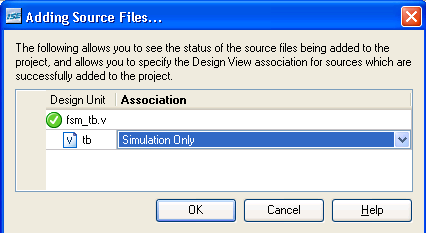
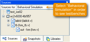
Project Navigator will identify that fsm_tb.v is a testbench for the fsm module, and will add it to the project source tree as shown below. You must first select "Behavioral Sources" from the pull-down menu at the top of the sources pane in order to see testbenches.)
Running ModelSim
ISE includes an interface for launching ModelSim from within Project Navigator. To use this interface, ModelSim must be selected as the default simulator for the current project. (To check or change the default simulator, right-click on the "xc2v6000-4bf957" item in the project source tree and select "Properties...".)
If a testbench file is selected in the source tree, the following processes become available in the process window:
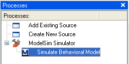
Double-clicking any of these simulation tasks will launch ModelSim and run a simulation using the selected testbench. (Note that each time you run one of these simulation tasks, a new copy of ModelSim is started. Since there are only a limited number of ModelSim licenses available for the class, please try to avoid running multiple copies of ModelSim at the same time.)
Behavioral Simulation
A behavioral simulation uses the Verilog source code you wrote in order to model the behavior of the module under test. Neither gate delays nor interconnect delays are modeled. Furthermore, functionality of the behavioral model may not match that of the synthesized logic, if you make use of Verilog language features that the synthesis engine cannot handle. (In particular, be careful about incomplete sensitivity lists.)
While behavioral simulation gives the least accurate prediction of how the final hardware implementation will perform, it is the most useful form of simulation during the initial debugging of a design. There is little point in running more realistic simulations until the behavioral model works correctly.
Behavioral simulation results for the example FSM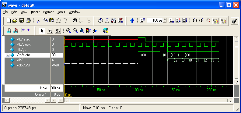
Non-Behavioral Simulations
Non-behavioral simulations are performed on some form of synthesized netlist. To simulate synthesized netlists of the fsm module, you need to fully synthesize the fsm module. You will need to set fsm as the top module first by right clicking on fsm1.
Generating synthesized fsm modules.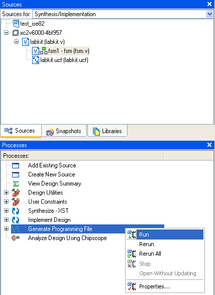
Post-Translation Simulation
A post-translation simulation uses the synthesized gate-level netlist to model the module under test. The functionality of the gates is modeled using a generic Xilinx library, but propagation delay is not modeled. The simulation should match the behavior of the actual hardware, but will assume the hardware is infinitely fast. (If you are worried about whether your design has synthesized correctly, start by checking the synthesis report file, as all common synthesis mismatch issues will generate warnings in the report file.)
Post-Mapping Simulation
In a post-mapping simulation, the gates have been mapped to a library specific to the FPGA device being targeted. This library includes accurate gate delay information. However, interconnect delay is not modeled, because the design at this stage has not yet been placed and routed.
Post-Mapping simulation results. Note the clock-to-state propagation delay of 1.2ns.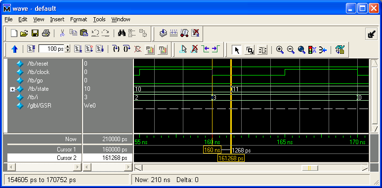
Post-Place-and-Route Simulation
A post-place-and-route simulation models interconnect delay, as well as gate delay. This type of simulation will most accurately match the behavior of the actual hardware. However, for large designs, it can take a significant amount of time to extract the interconnect delay values from the place-and-route information, and a significant amount of time to run the actual simulation.
It really only makes sense to perform post-place-and-route simulations at the top level of a design. If you perform a post-place-and-route simulation on a submodule, the place-and-route process is rerun, using the submodule as the top-level of the design. The interconnect delays for the submodule simulation will therefor not match the interconnect delays for that submodule when it is laid out as part of the complete project.
Post-Place-and-Route simulation results. The total clock-to-state propagation delay is about 4ns.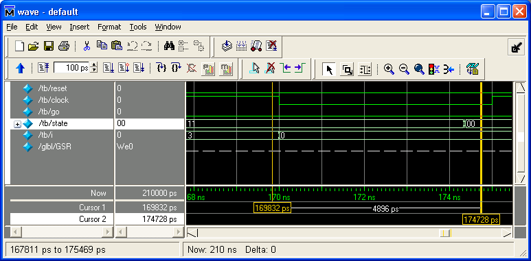
Solutions to Common Problems
- The ModelSim simulation tasks are not visible in the process window
ModelSim is not selected as the default simulator for the current project. Right-click on the "xc2v6000-4bf957" item in the project source tree and select "Properties...". Make sure ModelSim-SE is selected under "Simulator"
MIT 6.111 Introduction to Digital Systems, Updated February 04, 2007