
October-December 1998 Issue
Direct-Injection Automotive Engines:
New Insights for Designers
October-December 1998 Issue
Direct-Injection Automotive Engines:
New Insights for Designers
![]() ew vehicles with direct-injection spark-ignited (DISI) gasoline
engines offer high power and fuel efficiencies fully 30% higher than those
of conventional gasoline engines. The high efficiency of DISI engines stems
from their ability to run "fuel lean," that is, with a lower fuel-to-air
ratio than used in conventional engines. Smooth ignition, however, requires
a relatively "fuel-rich" mixture. The challenge in DISI engines is
therefore to capitalize on the lean part while ensuring a strong fuel-air
mixture at the spark plug. To provide adequate fuel vaporization and
transport to the ignition source, many designs use high-pressure fuel
injectors that provide swirl to the liquid fuel as it enters the combustion
chamber, creating a hollow cone of droplets that stays airborne long enough
to vaporize. However, Energy Laboratory experiments in a transparent test
engine show that the injected fuel may not always form a hollow cone. When
fuel temperatures are high or pressures in the combustion chamber are low,
the hollow cone can become filled in and more jet-like--especially when the
burning mixture contains components with low boiling points, as does
gasoline. The researchers' explanation? When the mixture enters the
combustion chamber, the low-boiling-point components suddenly vaporize with
enough force to shatter the liquid film. The tiny droplets that result are
sucked into the center of the disintegrating hollow cone. The MIT research
findings should help engine designers optimize the geometry of the
combustion chamber to ensure complete vaporization and easy ignition under
all engine conditions.
ew vehicles with direct-injection spark-ignited (DISI) gasoline
engines offer high power and fuel efficiencies fully 30% higher than those
of conventional gasoline engines. The high efficiency of DISI engines stems
from their ability to run "fuel lean," that is, with a lower fuel-to-air
ratio than used in conventional engines. Smooth ignition, however, requires
a relatively "fuel-rich" mixture. The challenge in DISI engines is
therefore to capitalize on the lean part while ensuring a strong fuel-air
mixture at the spark plug. To provide adequate fuel vaporization and
transport to the ignition source, many designs use high-pressure fuel
injectors that provide swirl to the liquid fuel as it enters the combustion
chamber, creating a hollow cone of droplets that stays airborne long enough
to vaporize. However, Energy Laboratory experiments in a transparent test
engine show that the injected fuel may not always form a hollow cone. When
fuel temperatures are high or pressures in the combustion chamber are low,
the hollow cone can become filled in and more jet-like--especially when the
burning mixture contains components with low boiling points, as does
gasoline. The researchers' explanation? When the mixture enters the
combustion chamber, the low-boiling-point components suddenly vaporize with
enough force to shatter the liquid film. The tiny droplets that result are
sucked into the center of the disintegrating hollow cone. The MIT research
findings should help engine designers optimize the geometry of the
combustion chamber to ensure complete vaporization and easy ignition under
all engine conditions.
In a conventional spark-ignition engine, fuel is injected into a hot holding area, the "intake port," before it enters the combustion chamber (the area inside the cylinder above the piston, where combustion occurs). As a result, much of the incoming fuel is vapor and thus easily ignited when the spark plug fires. However, the fuel may not fully vaporize in the intake port; and it may not completely mix with the air inside the cylinder before the spark plug fires. Conventional spark-ignition engines therefore need extra fuel to ensure ignition--a requirement that significantly reduces fuel efficiency.
Today's new DISI engines are designed to solve those problems. Liquid fuel is injected directly into the combustion chamber. By carefully designing the injector and the shape of the combustion chamber and top of the piston, designers induce flows that push the injected fuel toward the spark plug but along an indirect route that provides time for the liquid to vaporize. The injected mixture thus becomes "stratified": it is fuel-rich near the spark plug for easy ignition and fuel-lean elsewhere inside the combustion chamber. The direct-injection approach thus permits overall fuel-lean operation for high efficiency as well as other advantages including smooth acceleration, high maximum power, and potential emissions benefits.
Several companies have now introduced DISI models, with considerable fanfare about their high efficiency and other attributes. Yet research on this emerging technology continues. At MIT, Energy Laboratory researchers led by Simone Hochgreb have been investigating basic processes that may interfere with vaporization and stratification under some conditions, with potentially serious negative impacts. Incomplete vaporization can mean incomplete combustion, unburned fuel, and high emissions of hydrocarbons and particulate matter. And unsuccessful stratification can mean that the mixture near the spark plug is not sufficiently fuel rich for ignition.
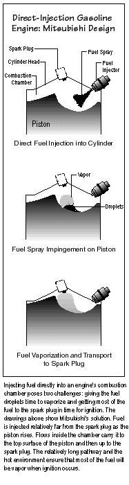 Designing a system that will prevent those outcomes is tricky.
Putting the injector near the spark plug ensures sufficient fuel for
ignition, but the fuel does not have time to vaporize completely and tends
to foul or wet the spark plug. A new approach is therefore to place the
injector and spark plug farther apart. The three drawings to the right show a
concept implemented by Mitsubishi. First the fuel enters the combustion
chamber. Then it impinges on the top of the rising piston and begins to
vaporize. Finally, it arrives at the spark plug in time for firing. Unusual
piston-head contours and special injectors help to create tumbling or
swirling flows that carry the injected fuel along the desired pathway.
Designing a system that will prevent those outcomes is tricky.
Putting the injector near the spark plug ensures sufficient fuel for
ignition, but the fuel does not have time to vaporize completely and tends
to foul or wet the spark plug. A new approach is therefore to place the
injector and spark plug farther apart. The three drawings to the right show a
concept implemented by Mitsubishi. First the fuel enters the combustion
chamber. Then it impinges on the top of the rising piston and begins to
vaporize. Finally, it arrives at the spark plug in time for firing. Unusual
piston-head contours and special injectors help to create tumbling or
swirling flows that carry the injected fuel along the desired pathway.
Developing all the details of such a system has required decades of theoretical and experimental work. Yet one aspect of direct-injection operation may have received short shrift. How the fuel travels inside the combustion chamber depends on the precise nature of the spray as it enters. How many droplets are there, how big are they, and how do they behave? Current designs are based on answers to those questions gathered in bench-scale equipment operated at room temperature. But the hot, high-pressure environment of the combustion chamber may change that picture.
Professor Hochgreb, Brad VanDerWege, and Michael Shelby have therefore been working to define the physical characteristics of the incoming fuel spray in an operating engine. They perform their experiments inside a transparent single-cylinder test engine consisting of a square piston that moves within a square "cylinder" with parallel glass walls that serve as windows for optical access (see e-lab, July-September 1994). To observe the entering spray, they use a technique called planar laser-induced fluorescence (PLIF). A laser beam is focused through a third, small quartz window. The burning mixture is "doped" with a compound that fluoresces in the laser light. The intensity of the fluorescence indicates the concentration of the dopant in liquid and vapor form. By creating an illuminated plane with the laser, the researchers can take photographs of the fuel's location as the engine operates.
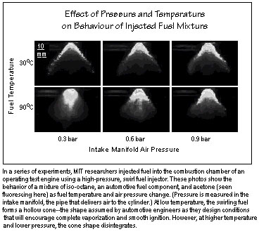
Fuel is injected through a high-pressure, swirl fuel injector. The injector is designed to create relatively small droplets that vaporize quickly and to give rotational movement to the fuel so it enters as a wide, hollow cone rather than a narrow, focused jet that would quickly reach the opposite wall. A thermocouple measures temperature in the cylinder head near the tip of the injector--an approximate measure of the temperature of the incoming fuel.
Early tests involved burning iso-octane, a component of automotive fuel, and acetone, a lower-boiling-point compound that fluoresces. The results were unexpected. The PLIF photos below show cross sections of the incoming spray at two inlet fuel temperatures (30oC and 90oC) and at three combustion chamber air pressures (0.3, 0.6, and 0.9 bar). (Conditions are described in terms of the air pressure inside the intake manifold, which delivers air to the combustion chamber at a controlled pressure. In this case, the manifold air pressure is roughly equal to the combustion chamber air pressure.) Each image was taken when the piston was halfway up the cylinder. The top left image, taken at 30oC and 0.3 bar, shows the expected hollow-cone structure--the structure observed in bench-scale, cold equipment. But in the lower left image, taken at the same pressure but at 90oC, the hollow-cone shape disappears. At the two higher pressures, the cone is again visible; but it is still somewhat disrupted at the higher temperature. Thus, when the temperature is high or the pressure is low, the fuel spray can take on a distribution that is not what designers have in mind as they optimize their direct-injection geometry and flows.
Because PLIF does not differentiate between vapor and liquid, the researchers could not directly determine the physical form of the material in the center of the cone. Is acetone vapor being entrained, or are acetone droplets also being brought in? To find out, they turned to a diagnostic technique called Mie scattering, in which a light shining on a cloud of material scatters wherever droplets are present. Those experiments confirmed that the material filling the cones does include droplets. Moreover, theoretical analysis based on the scattering images suggests that the mean droplet diameter in the case of the filled cone is roughly half the mean droplet diameter in the case of the cold hollow cone.
The researchers believe that their unexpected observations are caused by a process they call "disruptive vaporization." Acetone boils at about 56oC, compared to 99oC for iso-octane. As the fuel enters the hot combustion chamber, the more volatile acetone suddenly vaporizes, with enough force to shatter the rest of the mixture into small droplets. The large droplets that form initially have sufficient momentum to follow their own trajectory; they are unaffected by airflows and create the hollow-cone structure. However, the smaller droplets formed by disruptive vaporization tend to follow airflows induced by the swirling spray--airflows that draw them into the middle of the cone, where pressures are lower. This theory explains the effects of temperature and pressure. When the temperature reaches a certain level above the boiling point of acetone, the acetone boils hard enough to disrupt the overall mixture. However, if the pressure in the combustion chamber is high, the acetone cannot boil until the temperature is even higher. Thus, the higher the temperature or the lower the pressure, the greater the tendency of the acetone to boil and disrupt the incoming flow.
According to that theory, disruptive vaporization would be less likely with compounds that are less volatile, that is, that have higher boiling points (at normal pressure). To test that idea, the researchers performed experiments with two other fluorescing dopants: 2-butanone, which boils at 80oC, and 3-pentanone, which boils at 102oC. The array of photos below was taken during tests at 90oC. (The acetone results are repeated for comparison.) Clearly, the higher the boiling point of the dopant, the less disrupted the cone is.
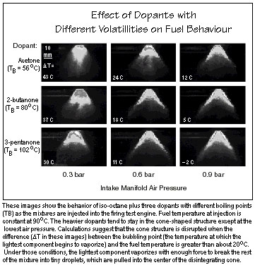
Based on their experimental results and theoretical modeling, the
researchers can estimate when disruption will occur. Their estimate is
based on the "bubble point," the temperature at which bubbles start to form
in a multicomponent fuel because the lightest component is beginning to
vaporize. According to their analysis, when the temperature of the fuel is
about 20=B0C above the mixture's bubble point, vaporization will be vigorous
enough to affect the structure of the spray, disrupting the hollow-cone
structure. In the images above, significant disruption is evident when the
difference between the bubble point and the fuel temperature (shown as  T) exceeds 20oC.
Gasoline itself is, of course, an extremely complex mixture that contains thousands of compounds with widely varying boiling points. Using PLIF to understand the fate of injected gasoline is difficult because only very heavy compounds in the mixture fluoresce. Mr. VanDerWege therefore created a simplified "surrogate" gasoline. He combined just five compounds with different volatilities to form a mixture that has the same distillation curve (mix of boiling points) that gasoline does. The compounds do not fluoresce, so they will not show up in a PLIF image--a feature that Mr. VanDerWege used to his advantage. In a series of experiments, he replaced three of the compounds (one at a time) with fluorescing dopants that have similar boiling points. The resulting PLIF images show where compounds with different volatilities go after they leave the injector.
The results were consistent with the disruptive vaporization theory. As temperatures go up and pressures go down, the heavier compounds remain in the hollow-cone structure while the lighter compounds fill in the middle. When temperatures are sufficiently high and pressures sufficiently low, the cone structure is replaced by a relatively straight jet. Even so, the more- and less-volatile components are separated, with the lighter materials in the center and the heavier ones more spread out.
The MIT researchers' findings are significant for designers of DISI engines. Given the observed effects of temperature and pressure, designers must find new ways to control the motion of smaller fuel droplets and more abundant vapor--a different task than influencing the large droplets they expected. On the other hand, the new insights may lead to novel design approaches. After all, smaller droplets vaporize more quickly than large ones. Disruptive vaporization could thus be an advantage. All in all, the findings from MIT provide designers of DISI engines with new food for thought.
Simone Hochgreb is an associate professor of mechanical engineering. Brad VanDerWege is a PhD candidate in the Department of Mechanical Engineering. Michael Shelby received his SM degree from that department in June 1997. This research was supported by the US Department of Energy. Additional support came from Zexel, Inc., and from the Energy Laboratory's Engine and Fuels Research Consortium, whose members are Chrysler Corporation, Ford Motor Company, General Motors Corporation, Mobil Corporation, Peugeot SA, Renault SA, Shell Oil Company, and Volvo Car Corporation. Further information can be found in references.