|
0. WAO Current Status
The WAO Camera was completed in February 2008. An Filterwheel upgrade is scheduled for August 2008.
Back View

Front View

1. Introduction
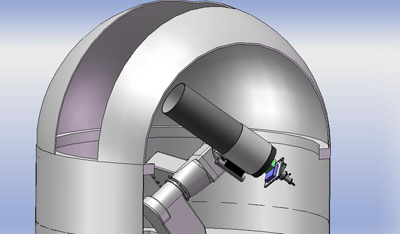
The WAO camera uses a SiTe 2kx2k CCD, identical to the one found on MagIC II. The permanent home for MagIC is the 24" Wallace Observatory in Westford, an hour away from MIT. The WAO camera consists of five components; i) instrument rotator, ii) field rotator, iii) filter wheel, iv) shutter mechanism, and v) the cryo-cooled dewar with electronics. The camera is run using a custom software package (LOIS) developed at Lowell Observatory. The plans for the camera is for educational purposes as well as scientific. The system will be used to track near-earth asteroids, exploration of the Kuiper Belt, and track occultations.
1.1 Design Goals
- Modular
- Low maintenance
- Easy to use
- High efficiency and throughput
- Minimal optics
- High quantum-efficiency detector
- Fast data readout
- Instantly accessible
- Mounted on 24" telescope
- Cryo-cooler
- Low power consumption
1.2 Technical Characteristics
The current WAO SiTe was the engineering chip of the Magic camera. The CCD functions as a grade 0 CCD, which is the reason for creating a camera system. The WAO dewar is always kept cold, cooled by a closed cycle CryoTiger to a detector temperature of -120 C.
2. Dewar
2.1 Design
The design calls for a vacuum seal container, maintained at -120 C. The vacuum should be able to hold for at least a two month period. The SiTe chip should be in thermal isolation from the dewar.
2.2 Window Specs
Window was ordered from Escoproducts.
S1-UV Fused Silica Precision
Window, Coated
3.500" +/-0.005" diameter x 0.1875" +/-0.005" thick
Precision optical polish, 1/4 wave flatness per surface,
40/20 scratch/dig surface quality,
Parallelism better then 3 arc minutes,
Nominal safety bevel on sharp edges,
MgF2 coated on two sides for visible wavelengths,
2.3 Window Transmittance

2.4 Schematics
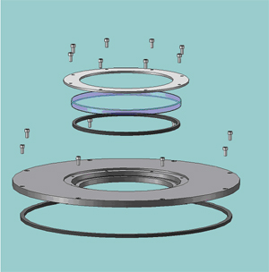
Dewar Front Lid Assembly Exploded View
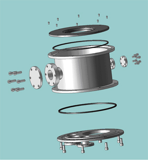
Dewar Exploded View
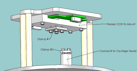
Dewar Interior
3. Shutter
3.1 Case Design/ Requirements
There are two purposes for the shutter: 1) control exposure time, and 2) obstruct the light path to the CDD when the camera is not in use. The shutter mechanism is the same of that used for the MagIC camera. The shutter case houses the shutter mechanism, so we can treat the shutter as an independent module.
3.2 Requirements
Minimize the space taken in the z-direction (direction along light path).
Hold a load of 50 kg in shear
Minimize beam bending effect
Light tight
Needs to be thin and hold the torque from the rear.
Be able to transfer forces without bending .001".
Must be light tight.
3.3 Stress Analysis
Stress analysis calcultions (PDF)
3.4 Schematics
E-drawing of Shutter
Picture of shutter - image of shutter
Inner workings of shutter
Download PDF of the Engineering Diagrams
4. Filter Wheel
4.1 Design
Six filter positions of 3" square filters
Controlled by Computer
Thin as possible
Withstand shear forces and torques
Light tight
Black anodized for protection
Easy to change filters
4.2 Stress Analysis
Stress analysis of case (PDF)
4.3 Capabilities
Six Filter Slots, one slot is left open. the other five slots are filters.
Additional filter fittings are available.
4.4 Control
Control interface should be LOIS or a Java Application running from a windows computer, sun or mac.
4.5 Schematics
E-drawing of Filter Wheel
Picture of Filter Wheel- image of Filter Wheel
Inner workings of Filter Wheel
List of Tools and Materials
Download PDF of the Engineering Diagrams
5. Telescope
5.1 Torque Calculation
Torque Calculation. (PDF)
5.2 Part Interfaces
Interfaces between parts. Stress Analysis. (PDF)
5.3 Optical Design
Mathematica Lenslab (PDF)
|