The MIT Course
in
Electromagnetism 2000
Vision
Motivation
Examples
Value Added
Time Frame
Table of Contents


Examples


I. Magnetic Force On A Currrent Carrying Wire


Consider the example of a straight wire carrying current in a background magnetic field, with the wire running perpendicular to the background field. The wire will feel a force that is both transverse to the background magnetic field and to the wire itself, reversing sign if the direction of the current reverses. This is an example of the transverse nature of the magnetic force, a concept that was greeted with general disbelief by the scientific community when first discovered by Oersted in 1821. It is also one of the harder concepts for the student to grasp, because a transverse force seems so counter to their intuition.

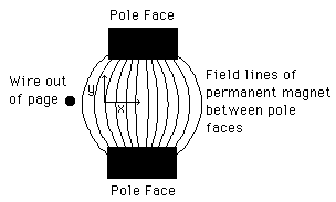
One demonstration of this phenomenon is as follows. A wire carrying a large current is moved close to the gap between the pole faces of a strong permanent magnet, as in the sketch. Depending on the direction of the current in the wire, the wire is either pulled into the gap (moves in the + x direction in the sketch) or pushed back out of the gap (moves in the - x direction in the sketch). A demonstration of this effect for both directions of the current in the wire can easily be put on a short video clip.


Typically this "push-pull" phenomenon is explained purely on the basis of the properties of the vector cross product--the force will reverse sign if the direction of the current reverses sign. A much more intuitive explanation, due to Faraday, is the following.

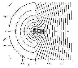
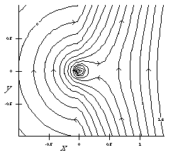
Consider the the overall magnetic field configuration in the two cases for the direction of current in the wire, as shown below. The view is looking down on the sketch above. For simplicity, we assume that the field of the permanent magnet is constant inside the pole faces and vanishes outside of the pole faces. The wire is sitting right at the edge of the region where we assume that the magnetic field due to the permanent magnet begins.

1.5 Meg MPEG

In the case above the background field is up and the wire carries current out of the page, so the force is to the left. Because the current is out of the page, the field lines circle counterclockwise about the wire, and connect to the field lines of the permanent magnet as shown.

0.5 Meg MPEG

In the case above the background field is again up and the wire carries current into the page, so the force is to the right. Because the current is into the page, the field lines circle clockwise about the wire, and connect to the field lines of the permanent magnet as shown.

Faraday would say that from simply looking at the topology of the field lines one can deduce whether the wire is pushed away from or pulled into the gap. And indeed that is true, if one simply thinks of the field lines as rubber bands. In the top sketch above, the field lines are trying to push the wire back out of the gap; in the bottom sketch, the field lines, if thought of as rubber bands, are trying to pull the wire into the gap.

This is even more obvious when one looks at the field topology as it varies with time. The animations of the two sketches above show the time history of the magnetic field lines assuming that initially the wire is moving toward the gap from the left at a constant speed.

The subsequent behavior of the wire is consistent with a simple view of the field lines responding like rubber bands. The pushing or pulling of the wire, depending on the sense of rotation of its fields and the way that they connect to the field of the permanent magnetic, follows naturally and intuitively.


II. Magnetic Torque On A Magnetic Dipole

Consider the example of a magnetic dipole sitting in a background magnetic field. The dipole will feel a torque that tends to align its dipole vector with the direction of the background field. This is the phenomenon one observes when using a compass--the compass needle aligns itself with the magnetic field produced by the earth.

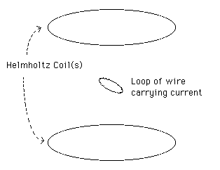
One demonstration of this phenomenon is as as follows. A loop of wire which carries current is placed in the magnetic field generated by a Helmholtz Coil, as in the sketch. The loop of wire is free to rotate around an axis perpendicular to the page. The loop of wire constitutes a magnetic dipole whose magnetic dipole vector is perpendicular to the plane of the loop, i.e., along its axis.


The Helmholtz Coil (actually two coils, as shown) produces a fairly uniform magnetic field near its center, directed along its axis. The loop of wire is placed at its center.

If the loop is initially at an angle to the axis of the Helmholtz Coil, it will feel a torque that tends to align its dipole vector with the axis of the Helmholtz Coil. In most introductory courses this torque is derived in a fairly clumsy way which is not particularly intuitive and which is immediately forgotten by most students. If we look at the magnetic field lines of the loop plus those of the Helmholtz Coil, however, we can see from the topology alone that there must be a torque that aligns the axis of the loop with the axis of the Helmholtz Coil. This is obvious from the sketch of the field lines of this configuration below.

1.2 Meg MPEG


This is even more obvious if one looks at the topology of the field lines as they vary with time. The animation of the sketch above shows the field lines as the dipole oscillates. The fact that the dipole feels a torque due to its interaction with the background magnetic field follows naturally and intuitively.

Moreover, with a little imagination one can clearly see that the loop as it oscillates is constantly exchanging angular momentum with the coils making up the Helmholtz Coil, through the intermediary of the magnetic fields. That point is never made effectively in an introductory course, whereas as it is reasonably obvious here.

Another interesting phenomenon to look at is the way that the fields of the dipole link into the fields of the Helmholtz Coil as the Helmholtz Coil is turned on. The animation below shows this time development. Initially the Coil is turned off, and then the current through the Coil increases linearly with time. The dipole loop is fixed in orientation, with constant current throughout. The dipole loop is not allowed to rotate in this process.

1.1 Meg MPEG


[next] [previous] [Page Top] [contents]

Comments (additions, modifications, suggestions)?

Copyright © 1996 John Belcher . All rights reserved.
Revised February 28, 1997, jwb@space.mit.edu