About Our System
|
About Our System |
KIT-MIT MEG Systemby Andrew Stringfellow |
The ![]() icon leads to relevant additional information
icon leads to relevant additional information
Click here for the same document
in the PDF format
The MEG system was provided by Kanazawa Institute of Technology, as part of a collaboration with the Applied Electronics Laboratory at KIT [1] (Tokyo, Japan). The same system is also developed and marketed by Yokogawa Electric Corporation (Yokogawa, Japan), and Eagle Technology Corporation. It is a recumbent system (the dewar is fixed in position). We refer to our system as 96 channels. In actuality, it contains:
The system includes 150 axial gradiometers in total. At present,
as indicated above, only 93 sites are recorded from. In the future we hope to
expand to using all gradiometers as recording sites. We have been rather fortunate
in that neither our move to a new lab site, nor the installation of the reference
magnetometers (which required warming the dewar to room temperature) damaged
the sensors that we currently use in recording.
In order for the MEG system to operate, the SQUID sensors must be kept extremely cold such that superconductivity is induced and SQUID effects are seen at the Josephson junctions. To achieve this end, the dewar requires 100L of liquid helium per week (liquid helium is -269°C/-452°F). We obtain our helium supply from BOC Gases (headquartered in Murray Hill, NJ, but we deal with a local distributor in Massachusetts). Technicians from BOC Gases perform the helium transfer as well.
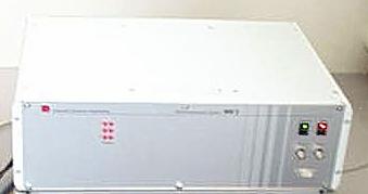
Data from the MEG system and other equipment are aquired by a DAQ system assembled by Eagle Technology. The system has four DAQ PCs and one control PC. Each signal is digitized with 12-bit resolution. Maximum sampling rate for raw data recording is 10kHz, and maximum sampling rate for evoked recording is more than 70 kHz. All inputs of the 96 channels can be displayed by four CRT monitors simultaneously. The DAQ computers are operated by Windows 98 and have 128MB RAM and 600Hz Cerelon processors. All of the DAQ PCs are controled by one PC which has higher graphical performance, 384MB RAM, and a Pentium III processor; the control PC runs Windows 2000. Both the DAQ PCs and the control PC are connected by Fast Ethernet and configure a LAN for data aquisition
For all data acquisition and MEG system control and maintenance, we use the MEG Laboratory software (aka MEG160), version 1.006E. This software is produced jointly by Yokogawa Electric Corp., Eagle Technology Corp., and Kanazawa Institute of Technology. The principal author of the software has been Yasuhiro Haruta, of Yokogawa Electric Corp.
For offline noise reduction using the 3 reference magnetometers, we also employ the MEG Laboratory software (see Software/Recording above). The offline noise reduction employs algorithms developed at the Applied Electronics Laboratory, specifically, the Continuously Adjusted Least-Squares Method (CALM [2]). The noise reduction procedure essentially eliminates any correlation that the data MEG sensors have with any of the 3 reference magnetometers by removing the detected covariance from the MEG sensors. This is performed data point by data point, with a moving window—typically, we use a six-second moving window. This means that each for each data point, the three seconds prior to it and the three seconds following it are used to determine the covariance between the MEG sensors and the reference magnetometers. This process was designed to eliminate low frequency (<10Hz) noise at Keio University (Tokyo, Japan), where a KIT MEG machine is also located. There, as here in Cambridge, large extramural magnetic noise from passing trains/subways can greatly disrupt MEG sensors. We are fortunate in that at our site noise from the MBTA Red Line, while large (at the current location it can exceed 20pT inside the MSR), is very stable in distribution—that is, it usually affects the same sensors in an almost identical manner. This stability facilitates both the CALM offline noise reduction, and the active compensation coil system (see MSR/active shielding below).
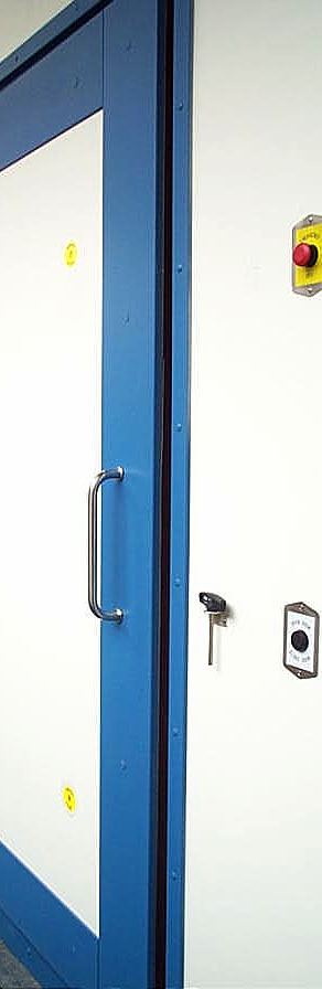
The magnetically shielded room (MSR) is a product of Vacuumschmelze (Hanau, Germany). The shielding effect is provided by two layers of mumetal (the inner layer is 3mm, the outer layer is 2mm). Predicted shielding performance was of –60dB at 1Hz; actual performance exceeds this prediction. The exterior dimensions of the room are 2.9 x 3.5 x 2.9m, and the inner dimensions are 2.4 x 3.0 x 2.4m. In addition to being very happy with the shielding provided by the MSR, we also appreciate the blue trim-on-white motif.
In addition to the offline CALM noise reduction system described above, we also have an active shielding system ("active compensation coils") designed by Vacuumschmelze, and incorporated into the MSR. The system senses the incoming (extramural) signal, and produces signals of compensating voltages to annul as much of that signal as possible. The system consists of:
Because the dewar/MEG sensors are not centered within the room, the precise locations of the compensation coils were adjusted by Dr. Jochen Bork of Vacuumschmelze so as to have the maximal cancellation effect.
To absorb any high frequency vibrations we have laid a .5" (1.275cm) thick sheet of rubber (actually 70 durometer neoprene, several sheets side-by-side) under the MSR. At our old site, vibrations had tended to induce noise as low as 16Hz into the MEG signal. We obtained the vibration pad from John G. Shelley Co. (Wellesley Hills, MA).
We record the location of the marker coils and electrodes on the subjects, as well as three fiducial locations (the nasion, and the left and right preauricular points). Additionally, we typically record the shape of subjects' heads (generally 1,000-2,000 points) from a Dell Optiplex PC. The hardware used for the digitization process is a Polhemus (Colchester, VT) 3Space Fastrak system with three receivers. Three receivers are placed on the subjects during digitization. The use of three receivers on the subject permits accurate correction in three dimensions for subject movement.
Locator software from Source Signal Imaging Inc., (San Diego, CA), part of the EMSE suite of applications, provides the user interface with the Fastrak.
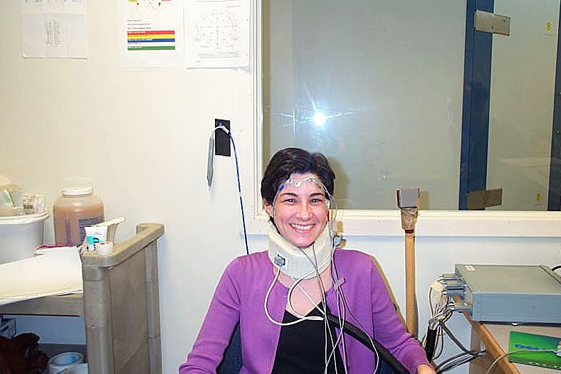
The lab has a bioamp system, for the monitoring/recording of spontaneous EEG signal (from ocular sites, used in the artifact rejection process), and for the recording of electric evoked potentials (eEPs) simultaneously with the magnetic evoked potentials (mEPs) that form the basis of the lab's research capabilities.
Our 24-channel bioelectric amplifier and headbox are products of SA Instrumentation Co. (Encinitas, CA). The amplifier is electrically and magnetically isolated, and run from a DC power source. The headbox will accept both loose-lead electrodes and electrode caps, and is inside the MSR.
For both the spontaneous and evoked potentials, we use electrode systems from Electro-Cap International Inc. (Eaton, OH). All electrodes are aluminum 9mm disks, except for reference and ocular electrodes, which are 9mm cups. Leads from the electrodes are made of carbon filament "wire." For evoked studies, we use custom-fabricated caps. These caps are standard in that they contain 19 data electrodes in standard 10-20 system placements (Fz, Cz, Pz, Fp1, Fp2, F3, F4, F7, F8, C4, C8, T3, T4, T5, T6, P3, P4, O1, and O2), as well as 2 electrodes for monitoring ocular signals. The standard ground electrode is located anterior to the Fz electrode. Custom modifications include the inclusion of 2 reference electrodes, the use of carbon filament "wire," the braiding of the individual leads as they leave the cap (to reduce electric noise on the MEG system), and the shaving of the housing of the posterior electrodes (to make the caps more comfortable, as this is a recumbent MEG system).
For both artifact monitoring and full cap evoked recording, we use two references, located on the left and right mastoid. The right mastoid is typically the site used as reference during data acquisition; electrode signals are then re-referenced to the left mastoid site during offline averaging.
Electrode impedances are kept below 10mΩ. To assess impedances, we use the EIM-107 Prep-Check Plus multi-lead impedance meter from General Devices (Ridgefield, NJ). We have found this to be a very handy device, being easily programmable to test at various thresholds and in various sequences.
Another helpful tool has been Johnson and Johnson's CIDEX OPA, which we use for disinfecting the electrodes and e-caps. This solution is much less volatile and corrosive than other disinfecting agents, and does not require a specially-vented fume/chemical hood for use.
Much of the video system was provided either wholly or partially by Nancy Kanwisher and her lab (special thanks to Nancy and her father, and Liu Jia; thanks also to Alison Harris, formerly an undergraduate working in Nancy's lab, and now a graduate student at Harvard University in the Vision Sciences Lab.
Our visual stimuli are computer-generated (Apple Macintosh G3 Power PC, 266MHz processor, 128GB RAM). The image generated on the Mac monitor is mirrored by an InFocus LP425 projector. The LP425 uses the Digital Light Processing (DLP) technology developed by Texas Instruments. This technology immediately transmits the image drawn on the LCD within the projector to its mirror-and-lens system, meaning that there is very little lag between the receipt of image information and transmission of the image (a large problem for the temporal accuracy of MEG experiments, if, as with other projection systems, a delay were present). The native resolution of this projector is 800 x 600, and our experiments either employ this resolution, or resolutions of 640 x 480 or 1024 x 768.
One issue that we ran into from the start, and that made the presentation of word stimuli for our language experiments especially difficult, is that the tube through which the image passes must be on a side wall of the MSR, rather than the front or rear wall (it can't be on the front or rear wall because the door and the dewar, respectively, present obstacles to projection). This doesn't sound as though it would be a problem at all—but the reality is the use of a side wall necessitates that the image be rotated by 90°. This is harder than it sounds. Lenses can only rotate 180°; similarly, our experimentation software too could only rotate 180°. To get around this problem, we use Pivot software (aka Mac Portrait) from Portrait Displays, Inc. (Pleasanton, CA). Designed to work with rotating monitors, this software lets us rotate the output of the Mac by 90°, and also lets us easily change the resolution and refresh rate.
Connecting the stimulus Mac and the InFocus projector proved to be a slight challenge—if the projector were fed from the Mac, some kind of conflict ensued and many resolutions and refresh rates were lost. To get around this problem, we use a special "hub," into which the Mac monitor and the projector interface. This hub came from InFocus (it's designed for people giving constant presentations); it is called the Cablewizard 2(although there might be a more recent sequel).
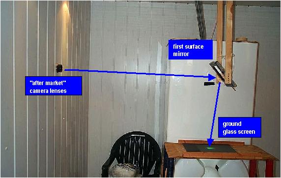 |
We have replaced the original lens system with several wide-angle camera lenses to produce a focused image size of approximately 18cm x 18cm (7" x 7") at a distance of 24cm (9.5") from the participants. The distance of the image from the projector is approximately 2.4m (8'). The image also enters the MSR horizontally, and must be reflected down. We accomplish this using a first surface mirror from Edmund Scientific (Barrington, NJ). This mirror is suspended from the ceiling and is fixed at a 45° angle; the incoming image hits the mirror and is reflected 90° straight down. |
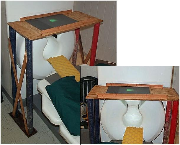 |
The image comes to rest on a ground glass "screen". The screen is held in a frame built by Nancy Kanwisher's father out of old fiberglass supports from a windsurfer. It's not pretty, but it's functional, as long as you don't mind the occasional fiberglass splinter. What is slightly unusual about the setup is that the participant is essentially viewing the back of the screen, rather than the front of the screen (and what we usually think of when we see anything project onto a screen). This means that the image is natively "backwards;" in order to fix this, we use the rear projection option on the LP425 to "flip" the image. |
The audio system is not especially fancy, but the routings are complex: we must be able to get auditory stimuli to the participant in the MSR, but we must also be able to speak to them through the audio system (the MSR is rather strongly sound-dampening). Additionally, we must be able to hear the participant outside the MSR, but also, if the experiment calls for a participant voice response, use the participant's voice as a trigger.
To talk to the subject, we use a standard unidirectional microphone that we must turn off at the start of experiments (to prevent feedback). To hear the subject, we have installed into a pass-through in the MSR an Audio-Technica ATM10a Omnidirectional Condensor Microphone (Audio-Technica U.S., Inc., Stow, OH); since the microphone is functionally inside the MSR, a condenser mike was necessary to eliminate RF noise.
Input from both the subject mike and the experiment mike are fed into a PreSonus MP20 preamplifier (Baton Rouge, LA). Here, we adjust the gain (in particular, boost the amplification of the subject mike). Input from the preamplifier (keeping the subject and experimenter inputs still segregated) is then fed into an Oz Audio (Boca Raton, FL) Qmix HM6 headphone matrix amplifier. There are six inputs, and four outputs, and the levels on each can be adjusted separately. Also feeding into the matrix amp is the sound (for auditory experiments and experiments providing auditory feedback) generated by the stimulus Mac G3.
Output from the matrix amplifier is sent to four destinations. A mix of the experimenter and the stimulus Mac output goes to the subject, via E-A-Rtone 3A insert earphones (AEARO Company, Indianapolis, IN)--the speakers are located just outside the MSR, and then the sound is fed to the subject via silicon air tubes, approximately 1.5m (5') long. A mix of the subject and the stimulus Mac output goes to the Mac speakers. Subject output is also sent directly and uniquely to a set of speakers close by, so that we can monitor the subject without hearing the computer output. Finally, subject output is sent directly to the button box (see below), to record voice-triggered responses. Additionally, we can use a fifth channel to record any combination of the subject, the experimenter, and the Mac-generated stimulus, if for example we should want to examine off-line the response produced by the subject.
At present, all of our experimental stimuli are administered from an Apple® Macintosh G3 Power PC, which has a 266MHz processor and 128GB RAM. All timing for experiments, and all responses made during experiments, are managed by the PsyScope Button Box (New Micros, Dallas, TX). This has millisecond resolution accuracy, and is not susceptible to the same drag that Mac and PC system "clocks" are. Responses by the subject are either voice-triggered (see Audio System/Output) or button-press, and are fed directly into the button box. The actual peripheral response buttons in the MSR are Specs® Switches, from Ablenet, Inc. (Minneapolis, MN). These have 2m (6') cords that extend to an adapter which converts the 1/8" headphone outputs to a 9-pin serial connector that is then fed into the button box. The adapter is of the homemade variety; formerly it was known as a Marantz box, but after some recent repairs it has come to be known as the Adachi box.
Stimuli are normally administered via the PsyScope program[3], version 1.2.5 (occasionally, bugs in this freeware force us to use version 1.2.2). We use this for both auditory and visual experiments. We are also set up to use the Psychophysics Toolbox [4, 5], which operates with Matlab software (we use Version 5, Release 10, for the Mac), from The MathWorks, Inc. (Natick, MA). Special code has been written by Satrajit Ghosh at Boston University (arranged via Nancy Kanwisher's lab) to run the button box from Matlab.
|
What is MEG? • About Our System • People • Being a Subject • Getting Here • More Info |