Theory
I. Carbon Nanotubes
Since their popular debut in 1991, carbon nanotubes have been a driving factor in nanotechnology engineering. Carbon nanotubes are cylindrical in structure and are allotropes of carbon. Allotropes are different structural modifications of an individual element, e.g. - diamond, graphite, and carbon nanotubes are all carbon allotropes (See Figure 2).
Adhesion of Carbon Nanotubes

Simulation Instructions
To download this application, press on the link above.
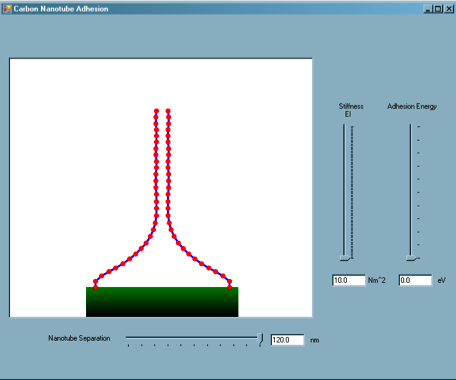
Once launched, the application is dynamic and constantly running.
Two vertically aligned carbon nanotubes are modeled, perfectly anchored to a substrate.
The user can manipulate the separation of the nanotubes, as well as the nanotube stiffness, EI, and adhesion energy between the nanotubes, thus representing nanotubes of different physical diameters, to explore the variation of equilibrium states of adhered nanotubes.
Download CNT.exe
Simulation Description
This simulation is meant to illustrate the balance between mechanical strain energy (elastic bending) and adhesion energy (weak molecular interactions) commonly encountered in carbon nanotube systems.
An understanding of this energy balance is critical for systems in which large groups of carbon nanotubes bundle, and can be utilized for the determination of carbon nanotube properties by microscopic imaging.
Credits
Program Author(s):
Webpage Author(s):
Advisor:
Citations
[1] Chen, B., et al., 2003. Binding Energy of Parallel Carb0n Nanotubes. Appl. Phys. Lett., 83 (17): p. 3570-3571.
[2] Baughman, R.H., Zakhidov, A.A., de Heer, W.A., 2002. Carbon nanotubes—the route toward applications. Science 297, 787–792.
[3] Treacy, M.M.J., Ebbesen, T.W., Gibson, J.M., 1996. Exceptionally high Young’s modulus observed for individual carbon nanotubes. Nature 381, 678–680.
[4] M.J. Buehler, “Mesoscale modeling of mechanics of carbon nanotubes: Self-assembly, self-folding and fracture”, Journal of Materials Research, Vol. 21, pp. 2855-2869, 2006
[5] Cranford, S., et al., A single degree of freedom ‘lollipop’ model for carbon nanotube bundle formation. J. Mech. Phys. Solids (2009), doi:10.1016/j.jmps.2009.11.002
[4] Liew, K.M., Wong, C.H., Tan, M.J., 2006. Tensile and compressive properties of carbon nanotube bundles. Acta Materialia 54, 225–231.


Copyright (c) 2010 Laboratory of Atomistic and Molecular Mechanics. All rights reserved.

Similar plots can be constructed as Figure 5 by varying either the stiffness, EI, or nanotube separation (bending displacement, Δ), and determining the energy minima.
III. Mechanics of Nanotube Adhesion, a.k.a. “Bundling”
For the past few decades, attempts have been made to understand and utilize the incredible strength shown by individual nanotubes. However, it is important to note that a common behavior of carbon nanotubes is inter-tube bonding, which causes bundles of carbon nanotubes that can even consist of hundreds or even thousands of individual nanotubes. The high axial strength of the individual carbon nanotubes is difficult to utitilize, however, when these bundles form. Even so, it has been observed that bundles comprised of larger single-walled nanotubes tend to be stronger than smaller ones [6].
Carbon nanotubes exhibit bundling driven by inter-tube bonding. This inter-tube bonding can form “bundles” of hundreds or thousands of nanotubes that exhibit very different characteristics than individual carbon nanotubes. Though individual carbon nanotubes are studied often because of their high strength, it is necessary to observe the carbon nanotube bundles due to the significant decrease in strength (due to nanotube slippage) experienced as a whole.
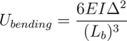
The weak van der Waals forces that hold the nanotubes together also govern the structural organization of the bundles. Our application is based on an energy balance consideration (see [5] for more details); bundle formation and equilibrium are described using bending strain energy, local deformation energy, and adhesion energy. The strain energy of a bent nanotube (fixed to a surface) can be described using beam theory:
Carbon nanotubes are simply rolled up sheets of graphene, which vary in diameter and length. There are two different kinds of carbon nanotubes that are essentially flawless in structure: single-walled carbon nanotubes and multi-walled carbon nanotubes. Single-walled carbon nanotubes (SWCNT) are made of a single graphite sheet wrapped in the shape of a cylindrical tube. Multi-walled carbon nanotubes (MWCNT) consist of a number of the cylindrical tubes, each fitting concentrically around another (See Figure 3).
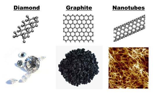
Figure 2: Forms of Carbon
Pure carbon materials come in different forms depending on the atomic structure of the material. Here, we show three allotropes of carbon: diamond, with a repeating 3D crystal structure, graphite, which is carbon atoms bonded in a common plane (single, pristine carbon sheets is known as graphene), and carbon nanotubes, which can be considered “rolled graphene”. Even with the same atoms, the bulk materials can be very different.
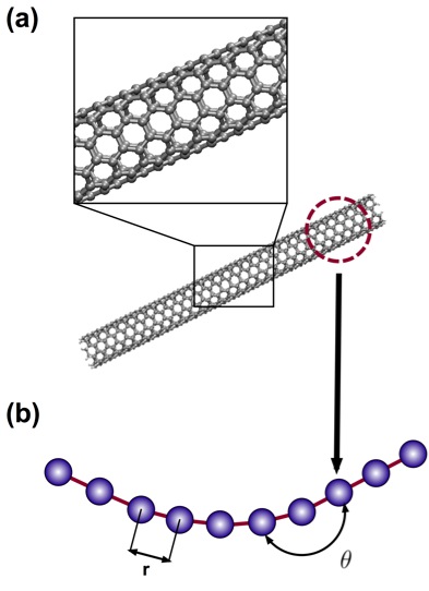
Figure 4: Full Atomistic v. Coarse-Grain Models
Schematic of coarse-graining procedure, in which full atomistic representation is replaced by a mesoscopic bead-spring model. Here, a pair of beads represents one nanometer of carbon nanoutube. (a) Full atomistic representation depicting all atoms and bonds (b) Developed coarse-grain representation, depicting bond lengths (r) and angles (θ) between bonded pairs and triples along the bead-spring chain.
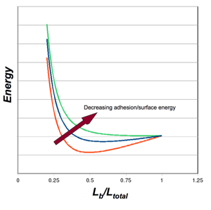
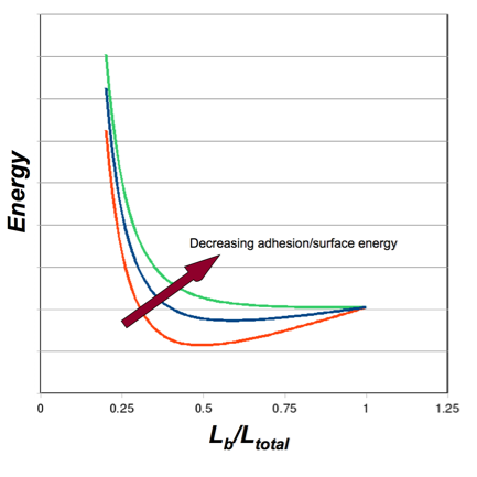
Figure 5: Energy Balance - Bending v. Adhesion
Plot of the total system energy as a function of the “bent” length of a nanotube (i.e. the portion that is not adhered). For illustration, three arbitrary values of surface energy are depicted. High surface energy (red) leads to increased adhesion, requiring more bending strain energy, and leading to less bent length (the strain energy increases as Lb decreases). As the surface energy decreases (blue), the location of the energy minimum shifts to the right, as less strain energy is required and more of the nanotube is involved in the bent portion. As the surface energy decreases further (green), there is no longer an energy minimum. There is not enough adhesion energy to bend the nanotubes to a point of adhesion/equilibirum.
This simulation is based on values from simulations and models developed by graduate student Steve Cranford from the Laboratory of Atomistic and Molecular Mechanics.
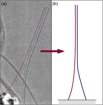
Figure 1: Adhered Carbon Nanotubes
(a) TEM image of two freestanding adhered carbon nanotubes (dashed lines added for clarity). Figure adapted from [1]. (b) Schematic of adhered nanotubes, corresponding to simulation arrangement.
The study of carbon nanotubes is one that is steadily growing with time due to their prospective use in various applications. Carbon nanotubes have the potential to be used in energy storage and conversion devices, conductive and high-strength composites, sensors, field emission displays and radiation sources [2], and much more. These structures are quite useful because of their optical, thermal, electrical, and mechanical properties. Mechanically speaking, carbon nanotubes display an extremely high strength [3] in terms of ultimate tensile strength and elastic modulus. The Young’s modulus for a single-walled carbon nanotube is approximately one Terapascal or 1012 Pascals (that's 1,000,000,000,000 Pa). To compare with other materials, steel has a (typical) Young's modulus of 200 GPa, or 0.2 TPa – five times less than carbon nanotubes. This strength is due to their seamless cylindrical graphitic structure.
Although possible, a full atomistic representation of carbon nanotubes is not necessary to investigate the bundling and adhesion behavior between two carbon nanotubes. Even a small carbon nanotube requires a lot of atoms for a full atomistic representation (over 100 for every nanometer in length!). Thus, our simulation implements a coarse-grain, or “super-atom” representation of a carbon nanotube.
II. Coarse-Grain “Mesoscopic” Model
A coarse-grain model was developed [4,5] by our lab to investigate the unfolding behavior of AH domains. define the parameters for the bead-spring model, carbon nanotube behavior can be determined by performing and observing various mechanical test cases at the full atomistic scale (aka atomistic “test suite”) [4] that establish Young’s modulus, bending stiffness, and adhesion energy – all the parameters required for the mesoscale representation. A coarse-grain representation is ideal because it reduces the number of effective parameters in study for molecular dynamic simulations; it is intended large-scale modeling of bundling as opposed to detailed behaviors. The mesoscopic model creates a relation between the total energy of the system and the system’s axial stretching, bending, and intra-molecular interactions, under the assertion of energy conservation. Local nanotube behavior is expressed through these potentials and a number of bead-spring components form the mesoscale model (See Figure 4).
We implement the model here to illustrate the bundling behavior between two nanotubes. It is possible without special simulation software because the coarse-grain representation utilizes less than 100 bead-spring elements. A full atomistic representation would consist of over 10,000 carbon atoms, with complex atomistic interactions, requiring the use of a supercomputer!
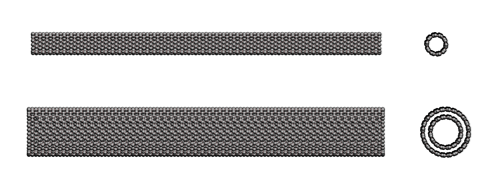
Figure 3: Single and Multi-Walled Nanotubes
Full atomistic representations of a small, single-walled carbon nanotube (diameter of approximately 0.6 nm) and a larger, multi-walled carbon nanotube with an inner and outer tube (diameter of approximately 1.6 nm)
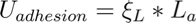
where EI is the bending stiffness of the nanotube, Lb is the bent length, and Δ is the displacement at the tip. The nanotubes are attracted to each other by weak van der Waals forces, which has an associated energy of:
where ξL is the surface energy (per unit length) of the nanotube and La is the adhered length. Simply put, if the strain energy required to bend the nanotube is greater than the energy of adhesion, the nanotubes to not bundle together. Conversely, if the energy of adhesion is greater, the nanotubes stick. For any tube with known stiffness and surface energy, plotting the total energy v. bent length can determine if the nanotubes will adhere: