![]()
Computer Modeling:
.::[Sketch Design]
.::[Design Development]
.::[Parametric Principles]
.::[Genetic Algorithm]
.::index>>
![]()
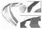
Sketch Design
The initial computer modelling was done in 3D Studio Max where we found that
using dynamic modifiers of the form gave a much more compelling
surface articulation than static modelling: it was as if
movement were captured in the ‘stretched’ facetting
that resulted. The basic form evolved from a blob that enclosed
a maximal surface-area increase, and this gave a compelling spiral as it swept
up from the lower balconies to envelop the entire roof terrace.
Thermal regulations on heat loss/gain determined the maximal
glazing as approximately 45%, and the requirement for view in all directions
determined that the surface be striated as solid/void. The form, subject to
twisting, resulted in a spiralling form that we articulated in varying scale
as it rose, matching facetting to curvature. The surface was facetted in respect
of fabrication potential, (we wanted to avoid complex-curved components) and
the solid elements given depth in anticipation of structural depth. These
models remained sketch designs, imprecise and essentially
unprincipled.
Design Development
As we began to articulate the form further, so we began modelling the form
more accurately, trying to understand the principles of such a complex form,
and the implications for fabrication. We undertook this task in Rhinoceros,
making several quick but essentially precise models. This allowed us to bed
down issues such as the basic structural diagram, and to begin to anticipate
the nature of the modelling and fabrication challenge. Nothing deflected our
basic assumption that such form could be modelled parametrically and fabricated
directly from our digital files using numeric command cutting of planar elements.
Ove Arup began to analyze the form in detail, requiring
that we provide accurate 3d models for analysis intuitively (to determine
load-paths) and then by a digital finite-element analysis.
Parametric Principles
As the project developed, so we began to articulate it in terms of parametric
principles, and we initially modelled these principles in Rhinoceros to discuss
them with the other consultants, principally the engineers, Ove Arup. This
resulted in a series of parametric ‘diagrams’ that helped clarify
the principles underlying the sketch ‘paramorph’. In this we tried
to think through the range of variables that the project seemed to require:
variability of the direction and proportion of the glazing; variation of the
structural depth of each solid element; variability of the depth of glass
from the façade surface (to avoid a thermal bridge); variability of
the overall form to limit height or overhang (anticipating complaints by neighbours
in terms of form or right to light), etc.
Latterly the project has been modelled in Bentley’s new
‘Generative Components’ software, which gave a simple parametric
model that could allow global variancy of the form: a central axis that can
be displaced like a joystick gives a malleability to the basic form; all elements
can then be twisted differentially around this axis to vary the facetting.
Each of the legs can be varied locally to open view or deepen the structural
form.
Currently we have moved to modelling the form in CATIA
where we are concentrating on the detailed level of articulation. Here we
combine parametric modelling with scripting to speed the generation of meta-components
(the legs and their associated glazing are built automatically via a generative
script), prioritizing the quadrilateral glazing panels and measuring their
discrepancy from the ideal complex-curved base ‘blob’. We are
currently using these to produce prototype assemblies that will be tested
for their performance by Arup.
Genetic Algorithm
We think of the project as one that looks to establishing the principles of
how one might articulate complex-curved form into a facetted fabrication system
where the facets are given thickness (to allow their edges to be machined).
This seems a sort of ‘Miesian’ principle when one accepts that
the computational environment is a curved paradigm. Yet it is a complex geometric
issue since offsetting triangles in 3d leads to anomalies in that they seldom
fall on single vertices springing from the nodes, thus giving little ‘errors’
that must be dealt with in the modelling and fabrication processes.
We have essentially avoided this problem by displacing
triangles inwards such that the ‘perfect’ triangulation of the
exterior face is maintained, with the machined internal edges accomodating
the anomaly. The glass has then been displaced in from the ‘ideal’
surface, and this, together with the determination that the glass should be
quadrilateral, has demanded a high degree of sophistication in the generation
of a parametric model.
.