Ultraluminous LED Light and Art Projects
Brian Neltner & Janet Fox
Updated July 23, 2010 with the new Light Brick System!
The Light Brick was used to excellent effect at the 2010 Burning Man Event by the Acoustic Combustion Camp. Ten light fixtures controlled by the Maple board from Leaf Labs were installed in a 30 foot geodesic dome and controlled wirelessly from a computer with input from the DJ in order to nicely flash in time with the music. Check out the Applications and Installations page for more information!
Here is a video showing the resulting lights and software installed in my room, playing a song by Eskmo (an awesome band!).
So I've mostly put my cloud coloring light on hold due to the complexities of building the switching power supply, until I have enough income that I can build several revisions to make sure that it'll work. Almost there though!
In the meantime, I decided I want to try to build a LED light specifically aimed at hobbyists who know how to do things like use an Arduino to output control signals, but don't know how to lay out LEDs, solder them, build cases, or build power supplies. The result is what I call the light brick -- a modular device with the throw power of full daylight at about 5 feet, with control entirely handled by giving it 18-36VDC, Ground, and a 3.3-5V digital input signal for red, green, and blue.
Complete details on the construction are now in a new dedicated section Light Brick!
They seem to work great so far, once I got past some minor issues with my new soldering techniques.Using this system, you can take whatever system you like, be it a computer, PIC, atmel, TI chip, Xbee, or whatever, to output signals that turn each color of LED on or off. Basically, a fully integrated, beautiful looking module that you can use to make really awesome LED projects without anything more complicated than an Arduino board.
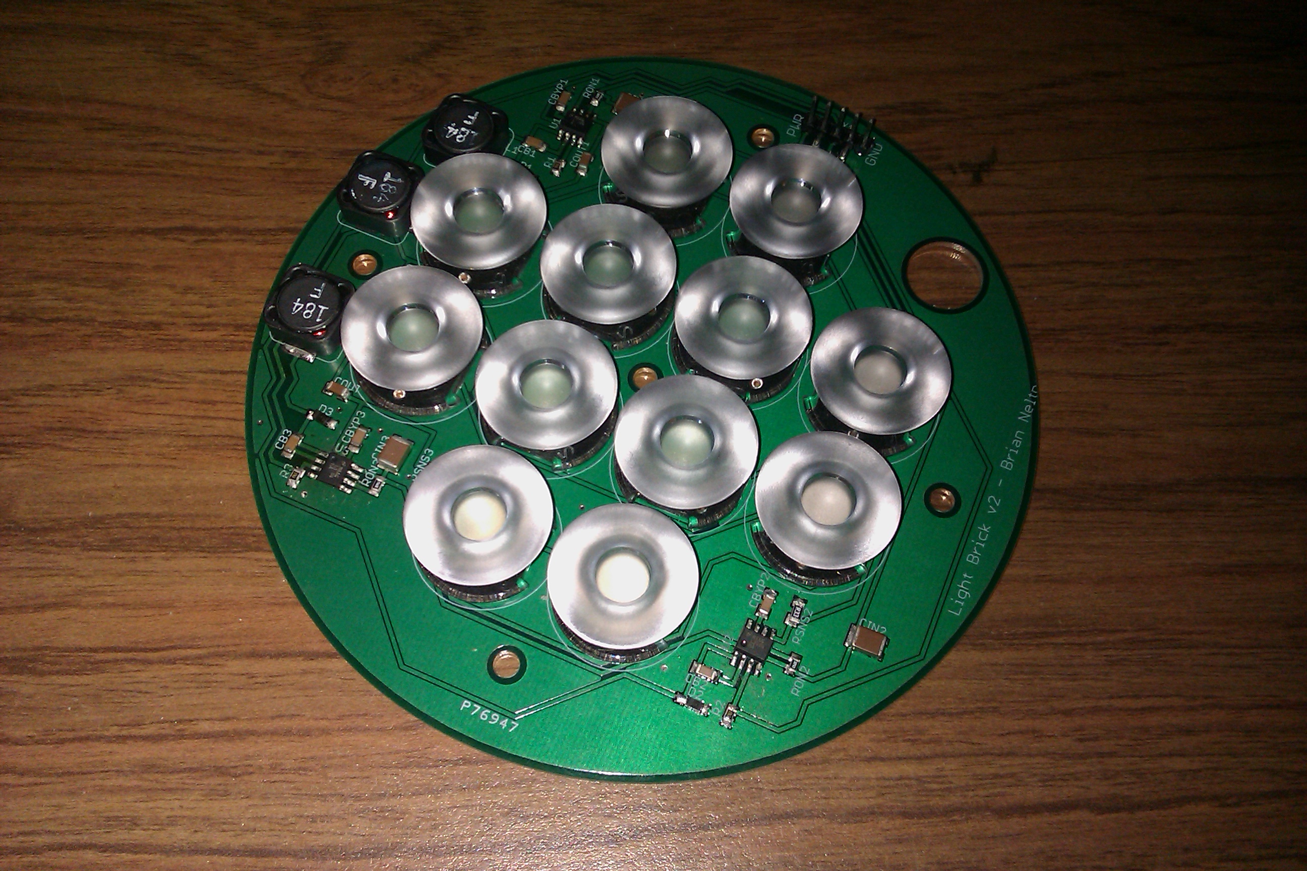
The design is a scaled back version of the cloud painter, with 4 LEDs each of red, green, and blue (LXML-PD01-40, LXML-PM01-100, and LXML-PB01-30) from Phillips Lumiled. Each LED has a 22mm lens that focuses the beam down to a 7 degree half-angle cone with a frosted lens to assist with making a smooth throw of light. Additionally, the board has three ~91% efficient switching regulators to guarantee that regardless of the voltage input (18-36VDC recommended), the LEDs receive 700mA. I also managed to route every single trace in the top layer of the board, so the vias are all only thermal ground vias, and there is zero risk of shorting something out by rigidly attaching the board to the aluminum case I designed.
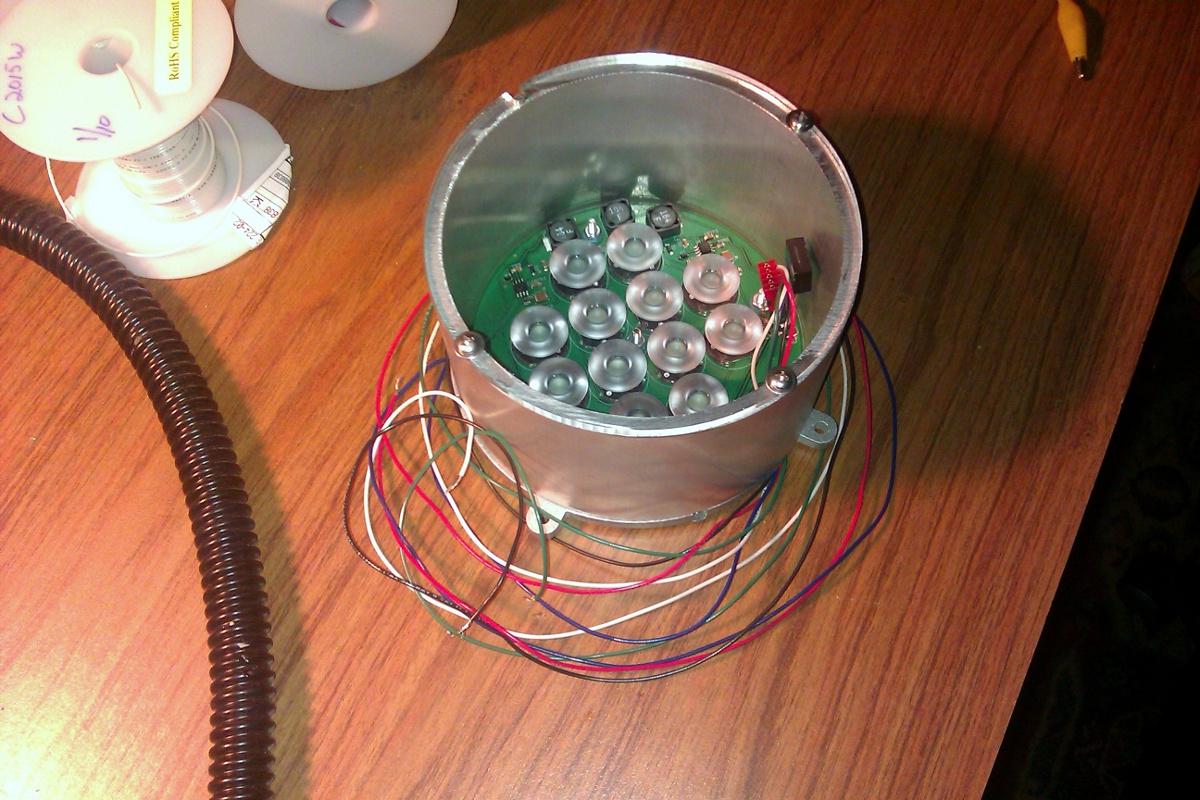
The end result is a board that sits in a 6" diameter, 3" tall aluminum case with an acrylic face plate and a hole in the back for control wires that throws an amazing amount of light for a fairly inexpensive cost. Boards have been ordered, parts have been ordered, and machine shop has been contracted, so hopefully it will be finished before burning man! Assuming 80% optical efficiency in the lens (which I think is about right) this will put out 272 lumens of red, 576 lumens of green, and 186 lumens of blue, for a total of 1034 lumens. Focused down in a 7 degree cone, that's a throw of 26000 lux at 3 feet, on the high end of estimates for the brightness of full daylight!
p.s. If you are so excited about something like this that you'd be willing to give me some cash to build them with, I'd be happy to send you one of the first prototypes in trade! If that sounds awesome to you, you can contact me! I believe that initially they are going to cost me about $325 to build them, or $240 without the case.
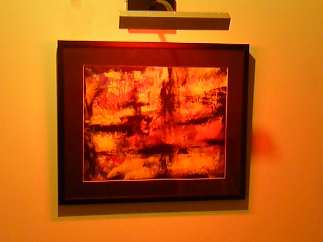
It's been a while since it happened, but I had my first big art show the weekend before Thanksgiving last November at the Brickbottom Annual "OpenStudios" event in Somerville. It was a great event, and I encourage anyone who lives in Massachusetts to come next year -- there were hundreds of artists, doing everything from large scale metalworking and forge work to pottery, to the lighting work that I do.
In any event, I've been planning a new light for the past few months which is finally coming to fruition. The basic idea was that although my current lights are beautifully suited for use in illuminating artwork with lots of color control and direct frequency selection, I wanted something more powerful. I also realized that the biggest hole in my electronics knowledge is building higher power power supplies, and so I could take out two birds with one stone by building an extremely high power light fixture with a home-built power supply.
The result is the concept of what I call the "Ridiculobright Illuminator", or fondly by my friends as the "Death Ray". The board consists of a 6" diameter circle, on which are 20 each of Royal Blue, Green, and Red Rebel Luxeon LEDs, running at 700mA. Each of my Ultrabright Illuminators have only four LEDs of each color running at 350mA, so this light should end up putting out roughly 10 times as much light as the Ultrabright Illuminators.
To make things even more absurd, I decided that I should put focusing optics on the device, which is something I resisted doing on the Ultrabright Illuminator because I was worried it would look funny. On the contrary, the focusing optics make the lights much better, because less light is getting lost on the sides of the case. I chose to use these 7 degree Dialight 11mm reflective adhesive based optics for the board, which had the advantage of being quite inexpensive.
After a bit of a SNAFU at Digikey where they sent me defective parts and then took two weeks to correct the mistake, I assembled the board and turned it on. This is, without a doubt, the brightest light I have ever seen -- the spot was easily bright enough to read by in a room across our house about 50 feet away just scattering off the walls. This light is truly able to be a "cloud painter", and let me make a cloud whatever color I choose.
Lumens are "luminous flux", a measure of the amount of light emitted from a source while candela are a measure of "luminous intensity", or power per unit solid angle. For this new light, with 20 LEDs of each color at 700mA, the total lumens is in excess of 5000 (5860 ideal, minus optical losses). Of course, the luminous intensity is in many ways more important than total lumens when you're talking about illumination -- if the center of the beam is the only place I care about, the luminous intensity is far, far higher than if the beam were unfocused (of order 100,000 candela).
The difficult part then is the power supply -- I have 20 LEDs in series for each color, which means a forward voltage of 60VDC for the blues, 64VDC for the greens, and 74VDC for the reds (measured with a multimeter at 700mA). Unfortunately, this high of a voltage means that standard power supplies I could buy wouldn't even be able to handle it, and it also substantially complicates the LED driver circuitry as they are only designed to run at up to 70VDC.
In any event, it's a difficult but not intractable problem. I have been looking at using the NCP1002 as an initial off-line regulator to provide a 100VDC bus capable of supplying 700mA, along with a 3.3VDC regulated output for controlling the digital chips on the board. I'm also looking at switching to using the LM3401, which is similar in concept to the LM3404, but with an external transistor.
In looking at how to accomplish this design, I was very surprised to discover that there are a variety of companies that will wind custom transformer cores for you, which is wonderful. In particular, MCE Magnetics helped me design a core, and is even going to send me some free samples to try to work through this prototype. What nice people, and based in the US too!
The case design I'm fairly pleased with as well. Keith helped me design it, and we think that it should have enough surface area to actually be passively cooled. I have included a SolidWorks built model showing what the light fixture will end up looking like. We have yet to decide how we want to put on a handle for attaching it to things, but that should be pretty straightforward.
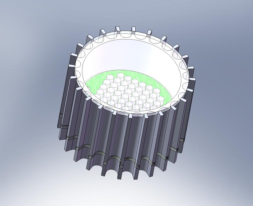
The idea with this is that the scalloped outside allows for higher surface area. I would have preferred more fins, but the end mill diameter is limited by the cut depth, so this is the best that was possible. We'll take a single 6" piece of 8" diameter aluminum stock and use a CNC mill to machine the entire piece at once, which should be pretty awesome to watch anyway as this is the largest machining project I've done before. Then, I will use a laser cutter to cut two pieces of acrylic to the appropriate shape to act as a cover, and also to act as an insulation barrier on the bottom of the light.
The bottom piece is where the power supply will be housed, and the only things that will run external to the light are the 120VAC power cable to a wall, and somewhere a little space for the XBee antenna to poke out so that I can control the light from a computer. The acrylic piece keeps the back heat sink from getting too hot and breaking the power supply, although from our rough calculations this shouldn't actually be an issue.
Heat was one of the biggest concerns in this project because of the far denser light generation on this board than anything done previously. This is why I chose to machine my own case out of thick aluminum to help heat make it to the outside instead of building up at the LEDs and risk burning them out. It should also make this by far the prettiest light I've made, especially if I anodize the case!
More updates to come as I make progress!
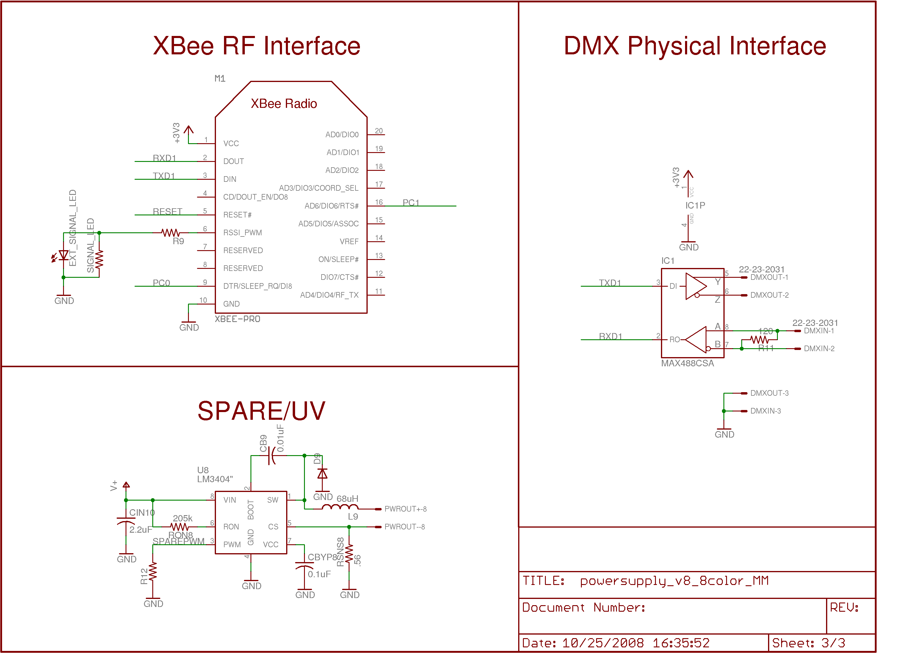
This is the first real update since early 2008, and a huge amount of progress has been made. The light fixtures are now on their eighth revision, have eight output channels (red, orange, amber, green, cyan, blue, royal blue, UV), have a built in power supply or can be run off of a 24VDC low-voltage line, are controllable over zigbee using the XBee interface modules, and all wiring is now entirely internal to the light -- no more monitor cable from the power supply to the light. Instead, I found a gorgeous hollow gooseneck designed for microphones that I can run all of my power inside of.
I also had the idea of protecting the user from the UV LEDs by coating them with a bubble of clear acrylic adhesive with very fine silica suspended in it. This seems to let a great deal of light through for the Rebel visible-color LEDs, and makes the apparent spot size about 8mm in diameter. This diameter should be enough so that even if someone removes the diffuser cover, they will be able to avoid eye damage. The acrylic adhesive is also quite permanent, I'd need to do quite a bit to get it off! Of course, this does *not* mean I am saying they are safe. Do not play around with the UV LEDs.
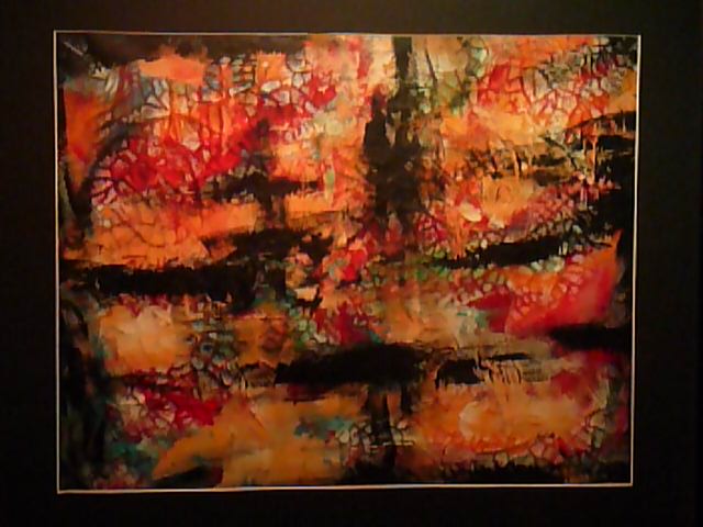
Here is a taste of the new work:
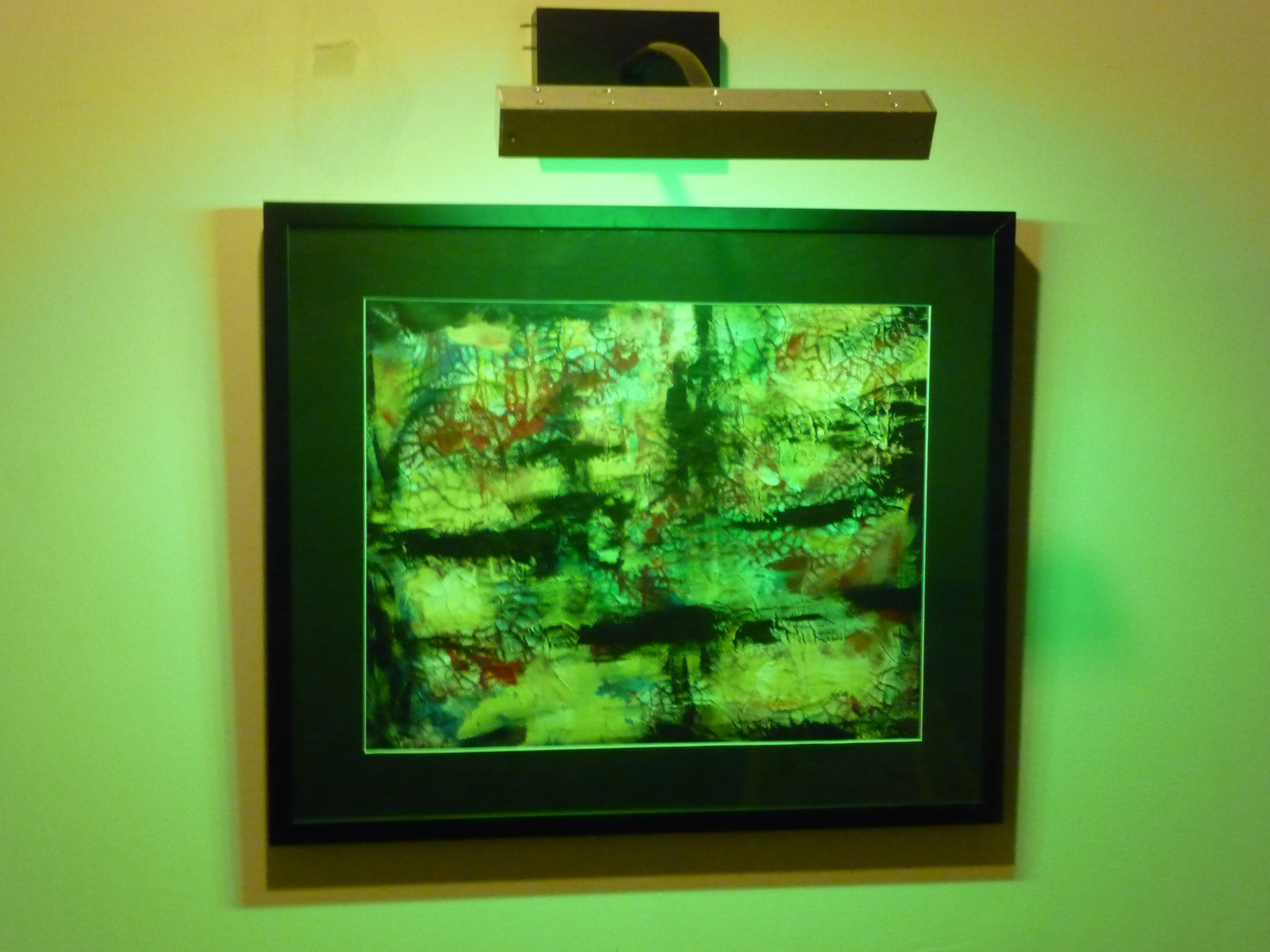
For movies of this new painting under the color changing lights, click below. The mode is set to randomly switch from one color of LED light to another. The first movie is filmed with the room lights on, which I think actually makes for a very nice more subtle effect. The second movie is filmed with the room lights off, which unfortunately also made the camera have a bit harder time focusing.
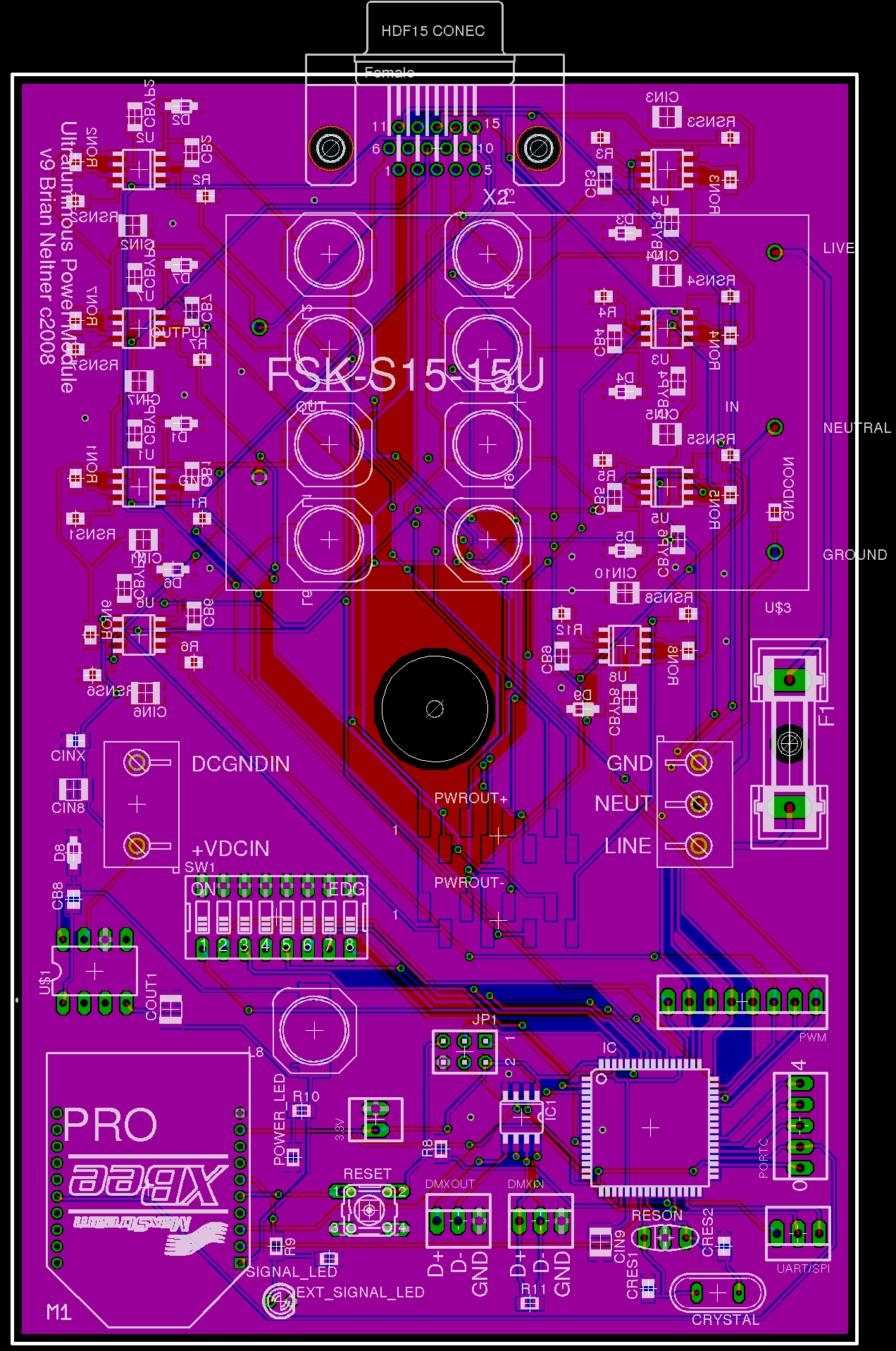
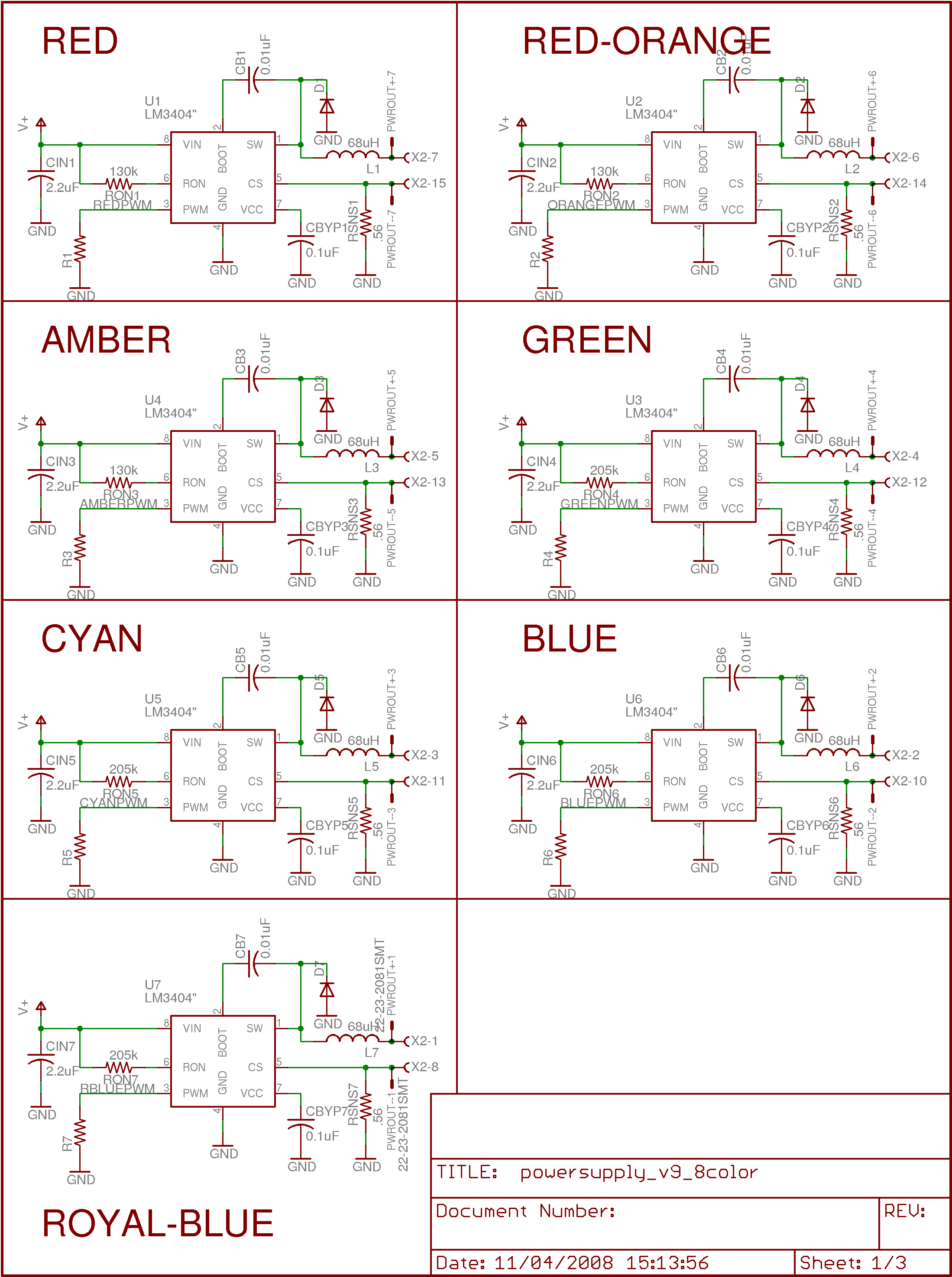
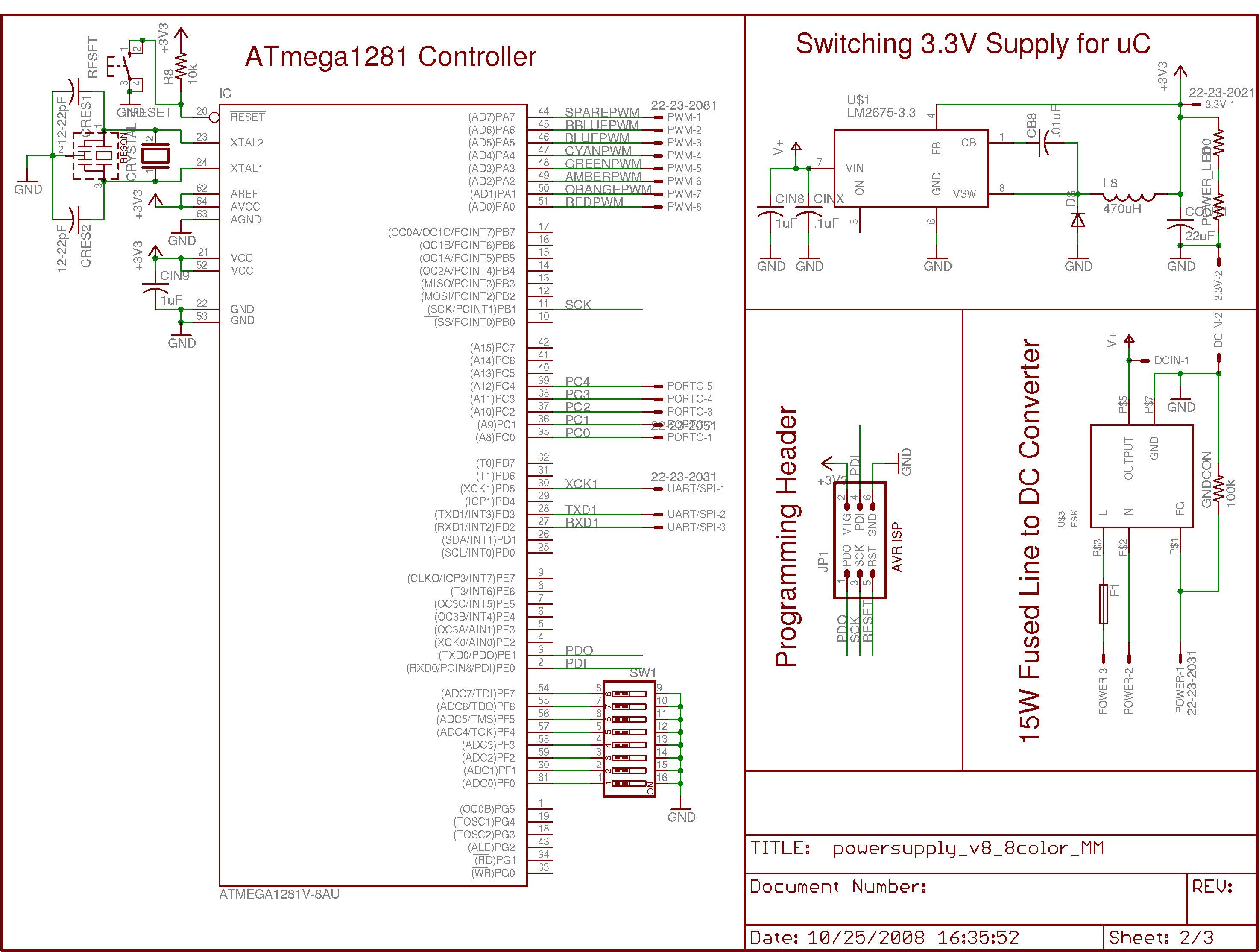
The circuit diagrams are being updated as well. This is the current version of the powersupply.
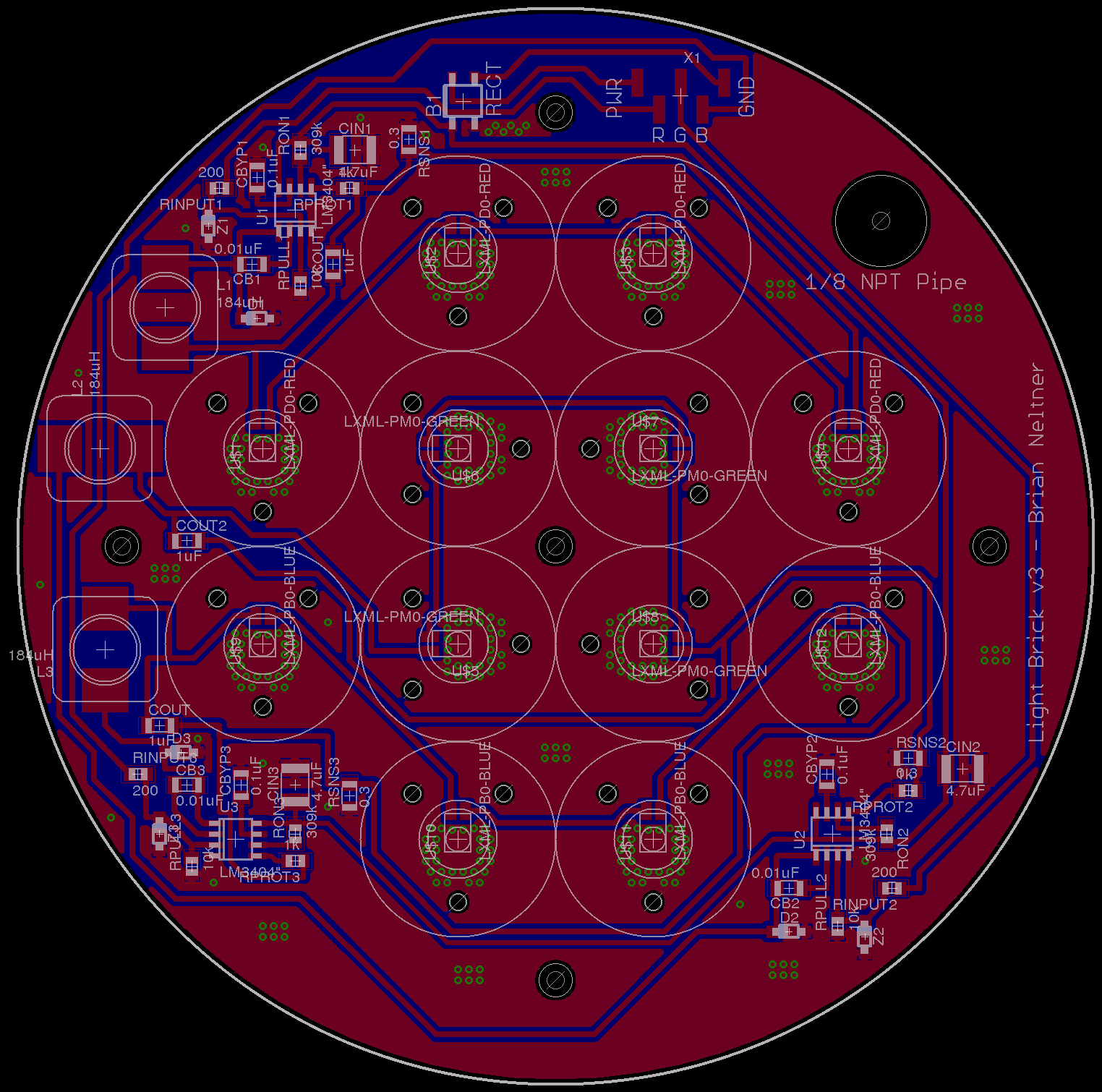
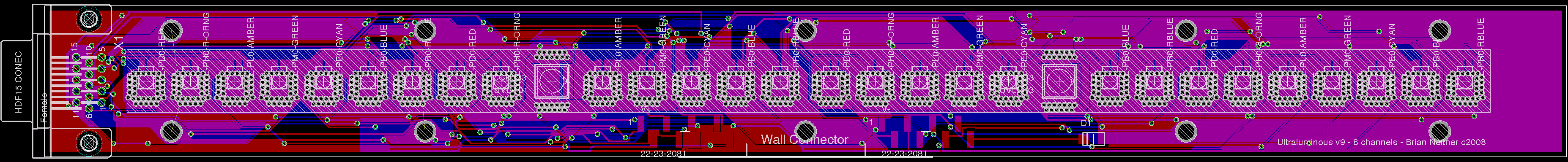
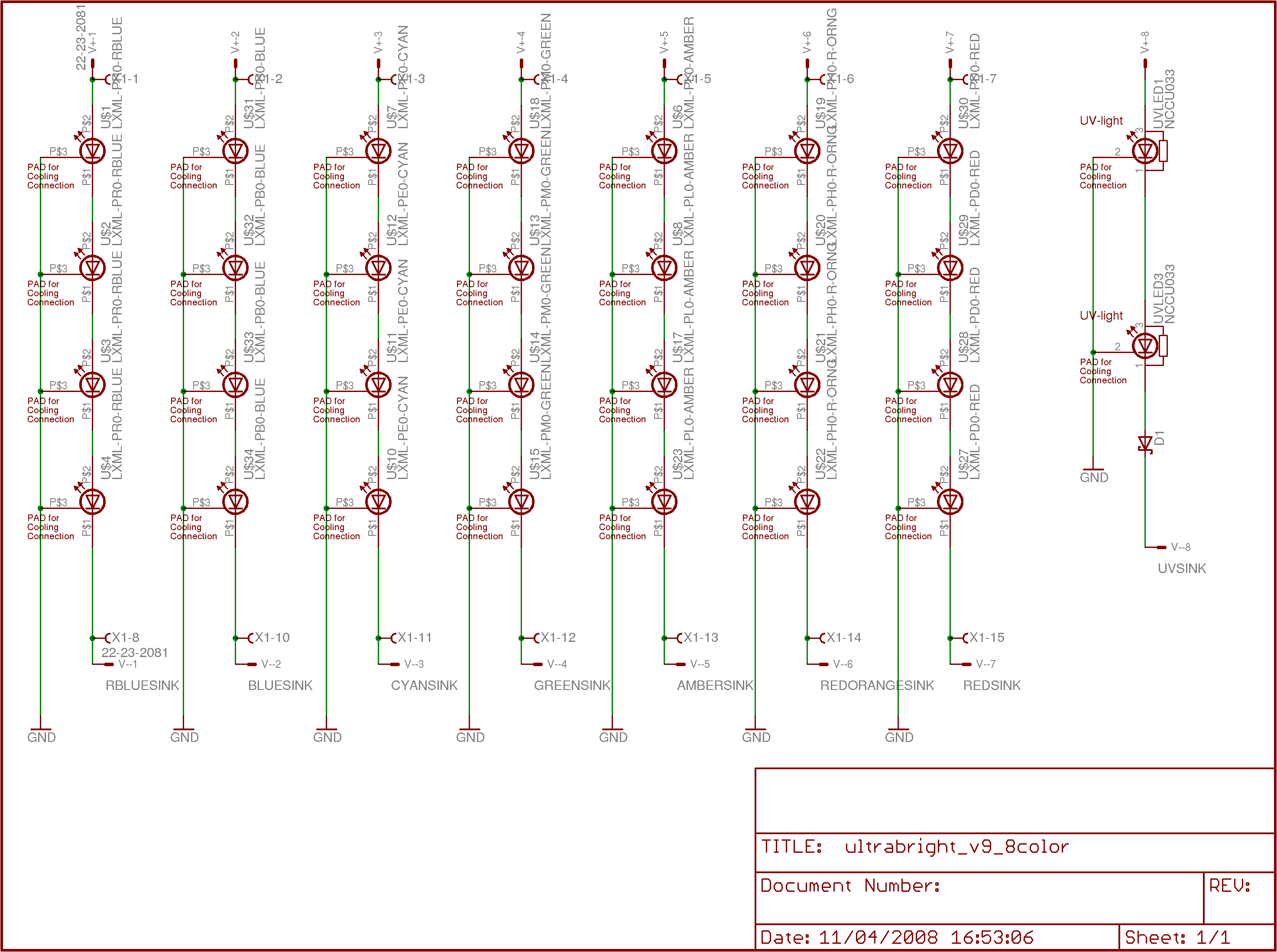
and this is the current version of the LED board.
Updates to the explanations have been made below in the "Details" section.
