Deepstar Experimental VIV Program
Offshore Tests
(Summer 2004)
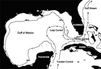
Gulf stream current
|
|
Motivating questions
Does lock-in occur at high mode number in uniform flows or sheared flow?
How is the boundary between single and multi-mode behavior affected by mode number, shear, and damping?
What is the relative contribution of in-line and cross-flow response to up-crossing frequency, stress amplitude, and fatigue damage rate?
How much fairing coverage is required to prevent significant VIV?
Can we measure hydrodynamic damping during VIV?
How does mean Cd vary with A/D and the number of participating modes.
Deciding on experimental program
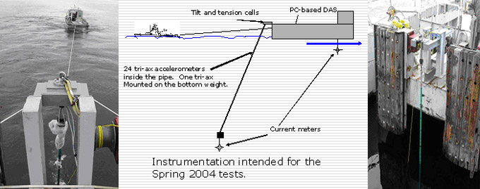
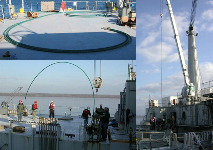
The desire for ease of mechanical handling together with a long fatigue life ultimately lead to the selection of a fiberglass coil tubing pipe for the testing program. The type of instrumentation was selected to be a network of triaxial accelerometers. This was decided after an investigation into various state-of-the-art technologies and whether they can be easily implemented.
Offshore Tests - The Gulf Stream Test: Overview (Miami II)
The Gulf Stream test was conducted in October 2006. The main objectives of the Gulf
Stream test were the following:
• Collect vortex-induced vibration response data on densely instrumented cylinder
responding at high mode numbers.
• Test full and partial coverage configurations for triple-helical strakes and fairings.
• Estimate drag coefficients for bare pipe and pipe covered with strakes and
fairings.
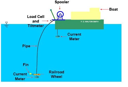
The Gulf Stream test was conducted on the Research Vessel F. G. Walton Smith out of
the University of Miami using a composite pipe of length 500.4 feet and an outer
diameter 1.43 inches. The length and diameter of the pipe were chosen such that high
mode numbers were possible; where high mode numbers are defined as modes greater
than approximately 10th mode. The experiments were conducted by towing the pipe from
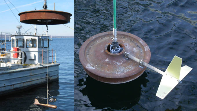
the boat. A railroad wheel, weighing 805 pounds in air and 725 pounds in water, was
attached at the bottom end of the pipe to provide tension. The pipe simulated a pinnedpinned
tensioned beam. The pipe’s dynamic response was tension dominated with the
bending stiffness of the pipe having negligible effect. Universal joints were used at both
ends of the pipe to create the pinned connection.
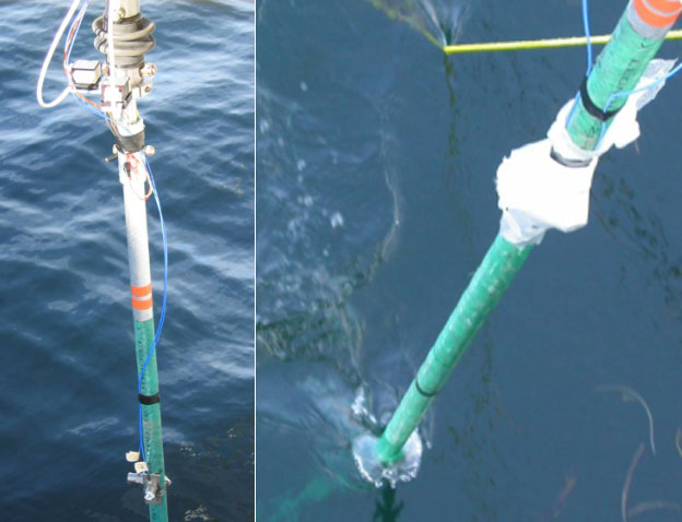
The pipe was instrumented with fiber optic strain gauges to monitor the vibrations.
Additional instrumentation included a tiltmeter to measure the pipe top end angle of
inclination, a load cell to measure the tension at the top end and two mechanical current
meters located near the top and bottom ends. A pressure transducer was also installed on
the railroad wheel in order to measure its depth. An Acoustic Doppler Current Profiler
(ADCP) was used to measure the magnitude and direction of the incident flow profile.
The properties of the pipe tested during the 2006 Gulf Stream test are listed below.
| Inner Diameter |
0.98 in. (0.0249 m) |
| Outer Diameter |
1.43 in. (0.0363 m) |
| EI |
1.483e3 lb ft2 (613 N m2) |
| EA |
7.468e5 lb (3.322e6 N) |
| Weight in Seawater |
0.1325 lb/ft (0.1972 kg/m) |
| Weight in air |
0.511 lb/ft (0.760 kg/m) |
| Density of pipe material |
86.39 lb/ft3 (1383 kg/m3) |
| Effective mean tension |
725 lb (3225 N, wet weight of railroad wheel) |
| Material |
Glass fiber epoxy composite |
| Length |
500.4 ft (152.524 m) |
| Manufactured by |
FiberSpar Inc. |
Insensys Fiber Optic System:
Fiber optic strain gauges were used to measure the vibrations in the pipe. Eight separate
fibers were embedded into the pipe during its manufacturing process at a radius of 0.685
inches from the center.
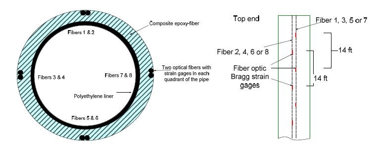
Each fiber contained 35 strain gauges. Two fibers were located in each of the four
quadrants of the pipe. The two fibers had strain gauges located every 14 feet; though the
strain gauges from the two fibers were off-set from each other to allow measurement
every 7 feet along the pipe. An Insensys Fiber Optic System (FSI unit) was used to record
the data. The system was limited to a sampling rate of 2000 Hz divided by the number of
strain gauges being sampled in the fiber.
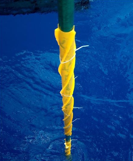
Strake Experiments
The strakes were a triple helix design made of polyethylene, with a pitch of 17.5 times
the diameter of the pipe. This represents a typical design for strakes in the industry. The
properties of the strakes are listed below. The strakes had a slit down the side that
allowed them to be snapped over the outside of the pipe. The strakes were then secured to
the pipe using tie wraps. The strakes were manufactured by AMS International.
| Material |
Polyethylene |
| Length |
26.075 in. (0.662 m) |
| Shell OD |
1.49 in. (0.038 m) |
| Shell ID |
1.32 in. (0.034 m) |
| Strake Height |
0.375 in. (0.0095 m, 25% of shell OD) |
| Wall thickness |
0.09 in. (0.002 m) |
| Pitch |
17.5 times the diameter |
| Weight |
0.11 lb/ft ±10% (0.164 kg/m, large
variation) |
Published Paper based on Gulf Stream Test Data
- Jaiswal, V. and Vandiver, J.K., 2007, "VIV Response Prediction for Long Risers with
Variable Damping", Proceedings of OMAE2007, OMAE2007-29353
- Jhingran, V. and Vandiver, J.K., 2007, "Incorporating the Higher Harmonics in VIV
Fatigue Predictions", Proceedings of OMAE2007, OMAE2007-29352
- Marcollo, H., Chaurasia H. and Vandiver J. K., “Phenomena Observed in VIV Bare
Riser Field Tests”, Proceedings of OMAE2007, OMAE2007-29562
- Swithenbank, S. and Vandiver, J.K., 2007, "Identifying the Power-in Region for
Vortex-Induced Vibration on Long Flexible Cylinders", Proceedings of OMAE2007,
OMAE2007- 29156
Lake Tests
The lake tests use all the equipment developed and put together by the team at MIT and its subcontractor SSI (Scientific Solutions Inc.). Additionally, DEEPSTAR have subcontracted BMT-SMS from San Diego to supply a data acquisition system which reads from a network of accelerometers. Each accelerometer is made to sample simultaneously, the information is held in memory and then sent to the surface packet by packet.
Click here for the full details of pipe properties.
The lake tests consist of two main configurations: