The actuator rods are what change the states of the bits. They are analogous to the logic rods of the Digi-Comp I. There are two actuator rods per control stage.
The actuator rods shown are for a single bit knex-i-comp. Additional segments are inserted in the middle for each additional bit.
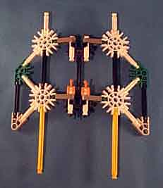
The picture shows two actuator rods as they would be attatched to the bit frame and bit frame top. The blue strut, blue connectors and white struts which serve as hinge pins are parts of the bit frame and bit frame top.
The red (arity 3) connectors and white struts provide sufficient stiffness so that the actuator rod doesn't flex during operation.
The gray (arity one) connectors on the left combine with white struts vertically mounted on the bit frame to form hinges on which the actuator rod can swing.
The blue struts, in addition to providing structure, will engage with yellow struts mounted on the programming hardware to alter the state of a bit assembly during phase 4 of operation.
The light gray (arity 2) connector near the bottom of the assembly engages with the actuator driver during phase 4 of operation.
The yellow strut at the bottom engages against the actuator back-block to hold the actuator rod off-normal during phases 2 and 3 of the operation cycle.