2.00b Toy Product Design
Thermometer CAD
Creating and Modifying 2D Features
The fundamental workflows of CAD are best understood by working through examples. Below, we'll show you how to add an example feature to the thermometer by going through the process of using the sketch, create, and modify tools. The tools and techniques we will use in this example are widely applicable not only in Fusion 360 but in almost any CAD software you will ever see!
Learn by example: Adding legs to the battery box
The base model is a pretty good thermometer. However, there are definitely things that could be improved. For instance, what if you wanted to set your thermometer down? You could lay it down, but that might take up a lot of space on your desk. Plus, it wouldn't look as cool :/ The obvious solution is to add nifty legs to the base so it can stand on its own.
We're going to begin by working in 2D. To start, add a sketch to the back of the box. To do this:
- Click the "Create Sketch" button:
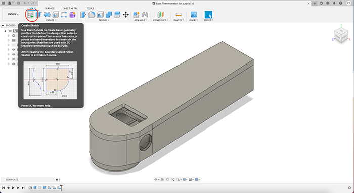
- Then, select the surface you want to create the sketch on. You'll be able to see the three default planes along the default X, Y, and Z axes, and you could start from that if you were starting a new model. In our case, we already have a body (the thermometer) there, so we can simply select the back case by clicking on it, as shown below (the cursor is represented by the red circle).

Here's a gif showing that entire workflow:

- After selecting the sketch surface, you'll notice that Fusion 360 has gone into Sketch Mode, giving you access to the sketch tool palette in the toolbar.

The palette is full of tools that make it easy to draw two dimensional sketches on your models.
- The create panel is for creating new sketch entities, and has tools that make it easy to draw polygons and lines.
- The modify panel is for modifying existing entities. For instance, you can round corners with the fillet tool or cut off parts of lines or geometries with the trim tool.
The constraints panel contains constraints that allow you to line your sketches to existing geometry. For instance, selecting two endpoints from two different line segments, and then selecting the "coincident" constraint will cause the points to be coincident and the lines will join at those points, creating a corner.
Constraints can easily trip a novice modeller up: applying too many constraints may cause conflicts (for instance, trying to make two line segments parallel and perpendicular simultaneously) that will cause errors or unexpected behaviors. This becomes trickier because Fusion will automatically apply constraints based on your sketching (for instance, automatically making points coincident if you sketch a line that ends on top of another line's endpoint). If a sketch is not behaving as expected, it's always a good idea to check for unexpected constraints.
Here are some of the many tools available in the sketching mode, all accessible from the top toolbar.
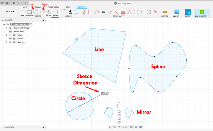
Tip: If you're curious about any of these tools, hovering over them will pull up a short explanation of their functionality.
If you click on the CREATE dropdown menu, even more options will show. One particularly interesting feature under the CREATE menu is the Sketch Dimension tool. While it's not particularly pressing today, this tool will become very important as you design models that have parts that need to be exact sizes.
Use the rectangle tool to create the legs. First, select the Rectangle tool. Then, click and drag on the back of the thermometer to create rectangles approximately where you want the legs to go.
If the angle of the thermometer makes it hard to perform this operation, you can use the cube in the upper right corner to adjust the orientation of the thermometer. This workflow is shown below:

Note that when you first draw your rectangles, they may be sized fairly arbitrarily based on the exact location of your mouse click. Naturally, as engineers we want nothing in our designs to be arbitrary! As shown in the gif above, we can use the "sketch dimension" tool to add dimensions to lines and features by first selecting the "sketch dimension" tool, selecting the feature we wish to constrain, and then inserting our own measurement or dimension.
After drawing your rectangles and assigning them appropriate dimensions, your sketch should look something like this:

Tips and Tricks!
If you mess up, always remember you can press Cmd+z or Ctrl+z to undo your most recent action, or use the two arrow buttons in the top left corner to undo and redo!
You can also delete individual sketch entities by selecting them with your cursor and pressing the delete key.
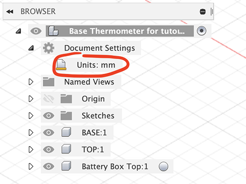
Ever want to change the unit system in your file? The setting is very easily changed in your browser, under "Document Settings."
Once you're done dimensioning, you can finish the sketch by clicking the green “finish sketch” button on the upper right.
Uh Oh! What if I accidentally finished my sketch too early, or I realize I want to go back and edit a sketch I've already finished?
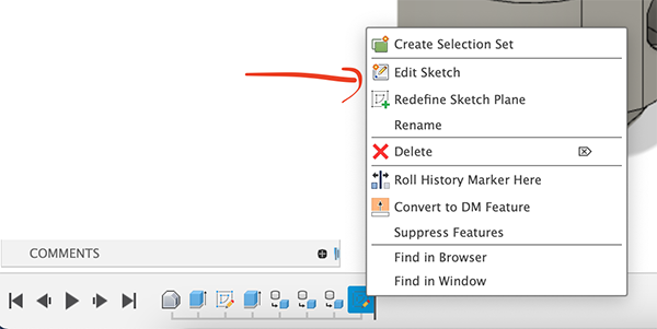
Never fear! You can always go back and edit sketches you have already finished. You can edit a sketch by double-clicking on it in the browser under the "Sketches" tab (but be aware it might be hidden, as Fusion will automatically hide sketches once you perform a create operation on them). You can also right-click on a sketch you have created in the design history along the bottom of your screen and click "Edit Sketch."
