

2.00b Toy Product Design
Thermometer Step-by-Step
Take temperature
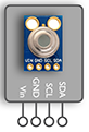
For our thermometer, we will be using an infrared temperature sensor. This sensor can be purchased by itself and wired up with a simple circuit, or it can be purchased on a breakout board with the circuit already prebuilt. We are using a breakout board version to save time and keep things neat.
Wire Stripping
There are many sizes of wire for various applications. The larger diameter wires can handle more current. For breadboards, 22 AWG (American Wire Gauge) solid wire is commonly used, so that is what we have. The larger the number of the gauge, for example 26 AWG, the smaller the diameter of the conductor.
Most wires have a conductor in an insulating sheath. The ends of the wire are exposed by stripping the insulation off. Wire strippers have holes that are sized for the various gauges of wire. Place the wire in the hole that corresponds to the gauge of the wire.
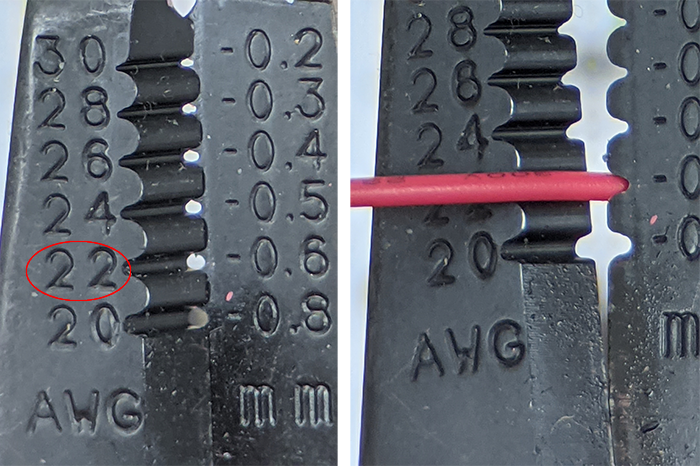
If the hole is too small, the conductor will be nicked. If the hole is too big, the insulation will not be fully cut and may be difficult to remove. Once the wire is in the hole, squeeze the handles tightly to cut the insulation, then pull the wire stripper away at a slight angle (see video below).
When wiring breadboards, it's a good idea to plan where the wire starts and ends before cutting and stripping the wire. Properly sized wires result in neater breadboards, and neater breadboards are usually easier to debug. One process for stripping wires is as follows:
- Strip one end of the wire, about a quarter inch.
- Bend the stripped end and place it in the start hole.
- Measure the wire to the end hole.
- Add about a quarter inch and cut the wire.
- Strip the newly cut end of the wire.
- Bend the newly stripped end and place the wire in the start and end holes.
If the start and end holes are difficult to reach, a different set of holes the same distance apart may be used as a reference instead. Watch the video below for a demonstration of the steps above.
Prepare the bus lines
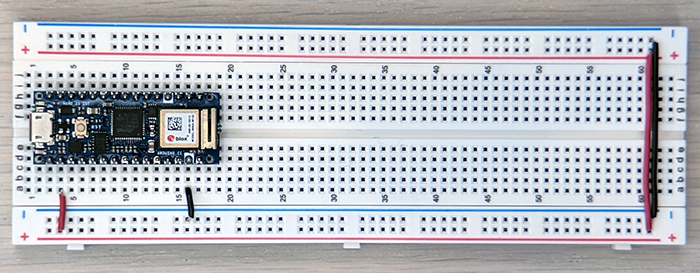
Our first step is to set up the power bus lines. Staying with convention, we will use the red busses for the 3.3V supply and the blue buses for ground. For this part, we recommend that you strip your own hookup wire to keep things nice and neat. While not required, it's good practice to use red wire for the positive power supply and black wire for the ground, if those colors are available. We will not only connect the microcontroller's GND and +3V pins to the busses, but we will also connect the busses on the two sides of the breadboard so that the busses on both sides of the board can be used.
Wire the following (suggested breadboard points in parenthesis):
- microcontroller GND (16a) to left-side blue bus
- microcontroller +3V (4a) to left-side red bus
- left-side blue bus to right-side blue bus
- left-side red bus to right-side red bus

Place and connect the temperature sensor
Place the IR temperature sensor on the breadboard. We recommend placing the first pin, Vin around 57e. We are leaving space on the board for the display and button. As much as possible, we don't want wires around or above the IR temperature sensor as that would hamper being able to get close enough to it to take a good reading.
Wire the IR sensor:
- Connect Vin (57a) to positive red bus.
- Connect GND (58a) to negative blue bus.
- Connect SCL (59b) to the Nano D19 (11b)
- Connect SDA (60a) to the Nano D18 (10a)
Test the thermometer
Download thermometer_test.zip (Right-click --> Save Link As...). Uncompress the folder and place it somewhere. From within the Arduino IDE, Open the thermometer_test.ino file that is inside the folder. Click Verify, then Upload. Then open the Serial Monitor to see the output. You should see the printout of the temperature reading 5 times a second for 10 seconds. To run the program again, hit the reset button on the Nano.
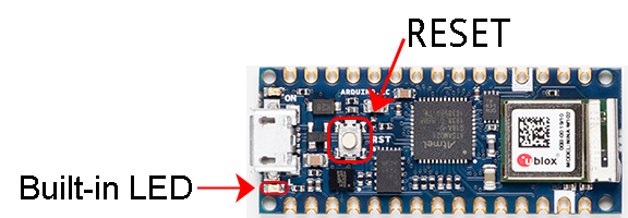
When the Nano resets, the built-in LED should rapidly flash while the Nano is restarting. If the built-in LED does rapidly flash, but you don't see new output on your Serial Monitor, try closing the Serial Monitor and opening a new Serial Monitor window for each reset.
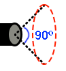 Try holding the sensor near different surfaces, including your hand, forehead and temple. Observe how the reading varies widely depending on how far you are from the target surface. This sensor has a 90 degree field of view and the optimal distance to the surface to be measured is about 1 cm. The value it provides is some sort of average over the surface it sees (red circle in diagram).
If you would like more or fewer readings to be taken before it stops, change the value of maxCount to a number different from 50. Be careful to leave the semicolon in place after the number! Then Verify and Upload again. Try this.
If the reading is an absurdly high value that is the same all the time, that usually means there is a problem with the wiring. A wire was probably put into the wrong row, so that it doesn't connect with the pin of the IR temperature sensor. There could also be a loose connection somewhere.