

Two- and Three-Force Members
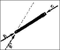
One of the unique aspects of these members is the fact that the line of action of the resultants of the forces acting on the two ends of the member MUST pass along the center line of the structural element. If they did not, the element would not be in equilibrium! Thus, even if a loading exists at either end that consists of only one of the components (i.e. Fx or y), the resultant of all of the forces acting on the two-force member passes through the center line of the member.
Most, but not all, two-force members are straight. Straight elements are usually subjected to either tension or compression. Those members of other geometries will have bending across (or inside) their section in addition to tension or compression, but the two-force principle still applies. There are NO EXCEPTIONS!!!
Some common examples of two-force members are columns, struts, hangers, braces, pinned truss elements, chains, and cable-stayed suspension systems. What are some others?
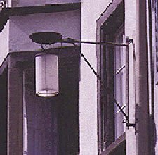
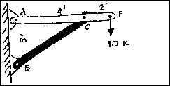
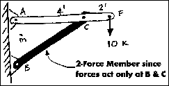
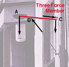
 Let us examine the simple
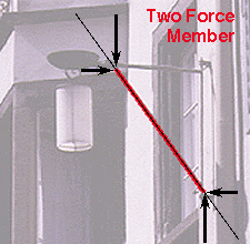
system shown. It is a simplification of the lamp indicated. The load at
point F is the hanging lamp. All of the joints are considered to be pinned.
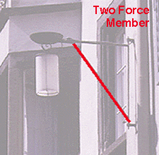
If member BC is isolated, it can be seen that it has forces acting at only
points C and B. This means that it is a two-force member. The line of action
of the force at point C must also pass through point B; similarly, a force
at point B must also pass through point C. If the force at B did not pass
through point C (B' in the diagram), the force would cause a moment about
point C and equilibrium would not be possible. Because the two forces are
equal in magnitude, co-linear and opposite in sense, two-force members act
only in pure tension or pure compression. Supports such as cables tend to
work well as two force members.
If three non-parallel forces act on a body in equilibrium,
it is known as a three-force member. The three forces interact with
the structural element in a very specific manner in order to maintain equilibrium.
If a three-force member is in equilibrium and the forces are not parallel,
they must be concurrent. Therefore, the lines of action of all three forces
acting on such a member must intersect at a common point; any single force
is therfore the equilibrant of the other two forces. A three-force member
is often an element which has a single load and two reactions. These members
usually have forces which cause bending and sometimes additional tension
and compression. The most common example of a three-force member is a simple
beam.
The lamp example also has a three-force member as part of it's structural
system. 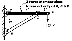
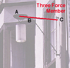
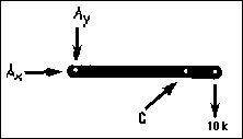
If one isolates member AF in the pin connected frame to
the right, one sees that it has forces acting at three points: A, C, and
F. The free body diagram of the system can be seen in the diagram below.
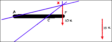
The magnitude and the line of action of the force at F, 10 Kips, is known.
The line of action of the force at point C is known because it must be equal
and opposite to the force C of the two-force member CB. The line of action
of the forces at point F and point C intersect at X. The line of action
of the force at point A must also go through points A and X. (Why is this?)
The lines of action of the reactions at points A and C have
now been determined. The problem of establishing their sense and magnitude
remains. The sense of these forces can be established intuitively in this
example, but this is not always the case. The Three Force Principle,
demonstrated in a step-by-step manner, will show how simple it is to establish
both the sense and the magnitude of the reactions of a system of three forces:
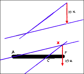
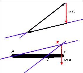
Had it been assumed that the line of action of the reaction force going through point A had taken a direction other than through point X, the system would not be a concurrent force system. Although it could be in force equilibrium, it would not be in moment equilibrium because the summation of the moments about ANY point would no longer be zero. This can be seen below.
The following is an example of the resolution of the support
force for the simple lamp system.


The third force vector is drawn along the line of action
passing through the second support. Now the sense and direction are known.
If the diagram was drawn to scale, the magnitude of all of the forces could
be simply determined using any graphical method of force resolution.
![]() Three-Force
Members
Three-Force
Members
hmmm.....
Schaeffer, R.E. Elementary Structures for Architects and Builders. Chapter
2.
Schodek, Daniel. Structures, Second Edition. pp 41 - 44.