|
|
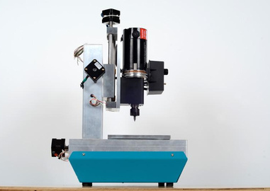
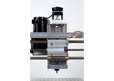
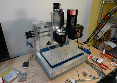
| Side view of the mill. |
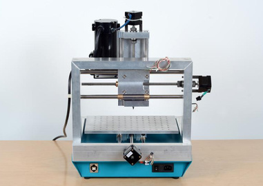
Back view of the mill. |
|
|
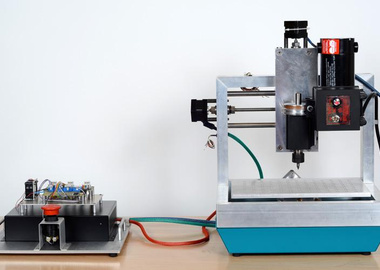
| The tool with an offboard EMC-based controller. |
Tight bends in the tube were achieved using a custom bending tool. |
|
|
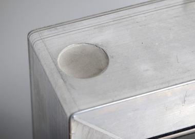
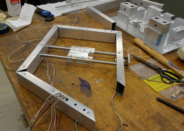
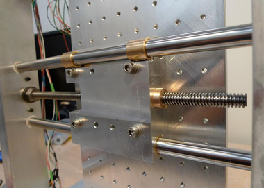
| Ports in the top of the X axis frame provide a fill point for pouring the cement. |
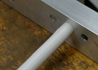
Precision guide rails pierce the aluminum frame thru oversized holes. |
|
|
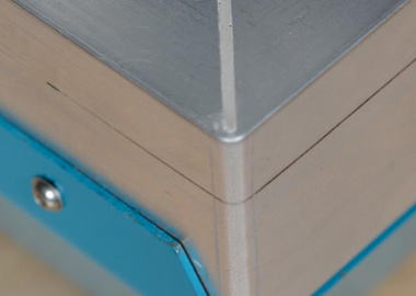
| The X and Y frames are butt joined with an internal aperture allowing cement to flow. This and a set of threaded rods reinforce the joint. |
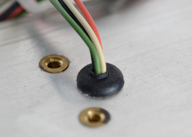
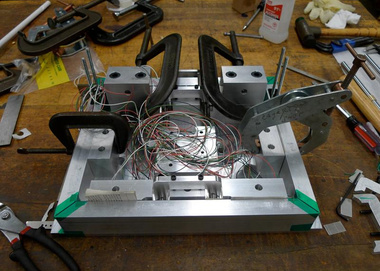
Motor wires run internal to the frame to minimize cable clutter. |
|
|
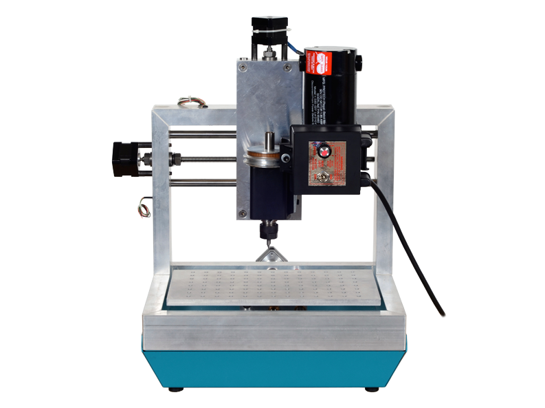
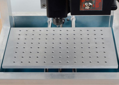
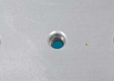
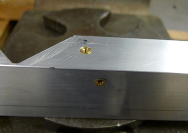
| The work surface is machined from cast aluminum and has 104 mounting/locating holes for aligning and fixturing work. |
The upper section of each hole is reamed for a locating pin, and the lower section threaded for a screw. |
|
|
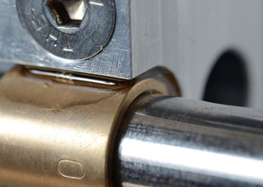
| The Z axis is mounted to the X axis in a stacked configuration. |
Each carriage has a set of fixed and floating bushings. The floating bushings are epoxied in a way intended to resist shear. |
|
|
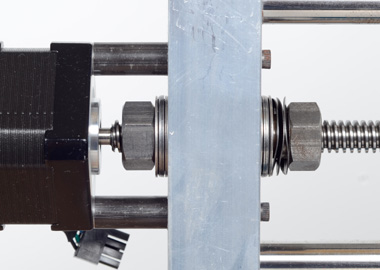
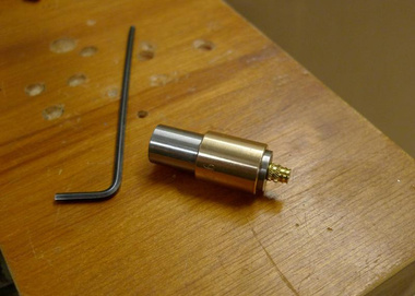
| Leadscrew preload assembly. |
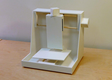
A foamcore mockup of the machine architecture. |
|
|
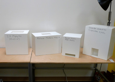
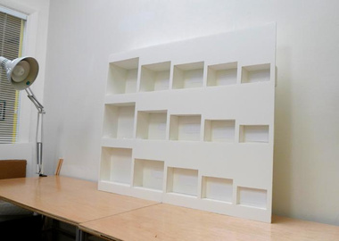
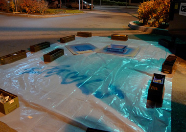
| Work began with a size-to-work-volume study of the competition. |
This set of cubbies helped determine a good working volume for the machine by testing which objects would fit. |
|
|
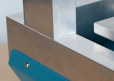
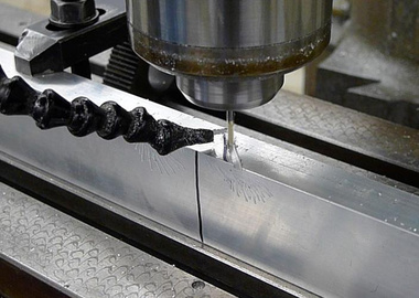
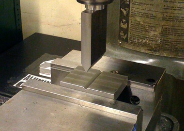
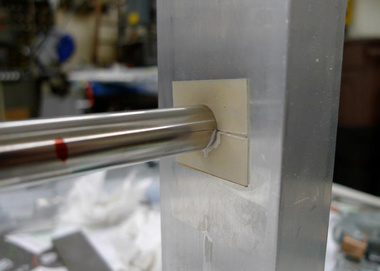
| V-cuts in the thin-walled aluminum tubing were machined for locating accuracy. |
The X and Y axis frame tubes post-machining. |
|
|
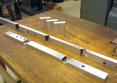
| A tool was made to assist in press-fitting inserts into the tubing. |
Press-fit inserts create mounting features in the tubing. |
|
|
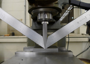
| An impromptu press-break using a Bridgeport milling machine and a custom knife and die. |
Bending the aluminum tubing. |
|
|
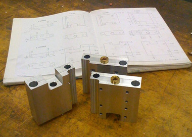
| Each carriage block was machined, with the intention of eventually extruding the profile. |
The Y axis frame during assembly. |
|
|
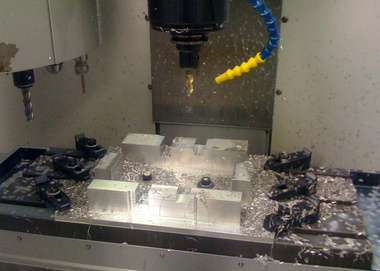
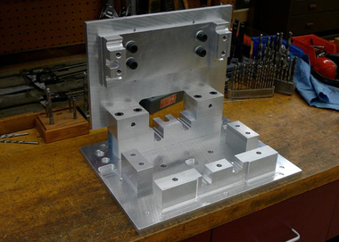
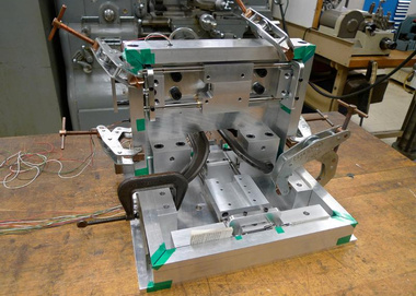
| The casting fixture was too tall to machine with an end-mill in one piece, so blocks were added as the machining progressed. |
The complete casting fixture is comprised of multiple assemblies. |
|
|
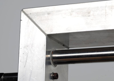
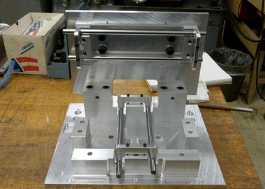
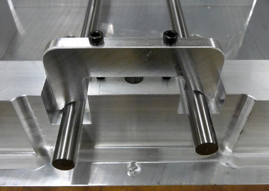
| Dry-fitting the guide rails to the fixture to test parallelism. |
Paper tubing (originally for model rockets) was used to create pass-throughs in the frame. |
|
|
| Temporary masks seal the gap between guide rail and frame during casting. |
The Y axis frame fitted onto the fixture. |
|
|
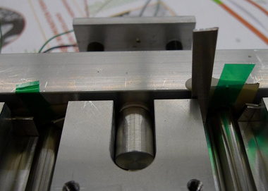
| Locating pins set the alignment between the motors and the carriages. |
Clamps repeatably bias the rails in their fixture seats. |
|
|
| Everything mounted on the fixture and ready for casting. |
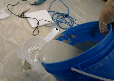
Pouring cement. This photo is of a trial run conducted without the fixture. |
|
|
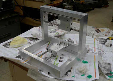
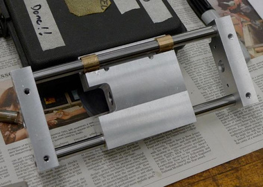
| The frame just after coming off the fixture. |
Mounting the table to the Y carriage. |
|
|
| The Z axis stage. |
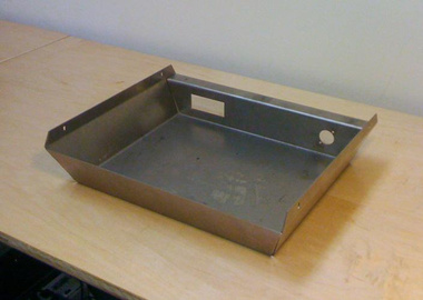
The electronics enclosure was bent from a sheet of waterjet-cut steel. |
|
|
| Painting the electronics enclosure late at night. |
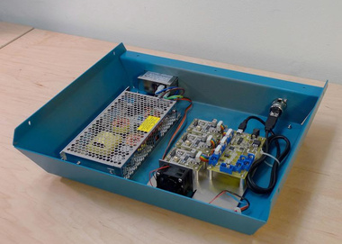
Originally, the control and drive electronics, and the power supply, were housed inside the machine. |
|
|
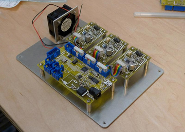
| Motion control would have been done using custom firmware and driver boards. |
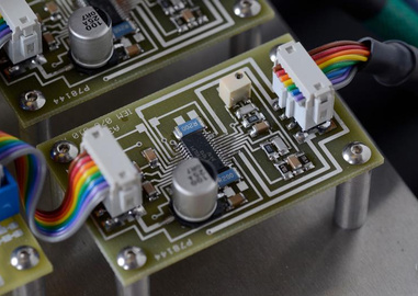
Close-up of a custom Allegro A4982-based stepper driver (same as used in prior projects). |
|
|
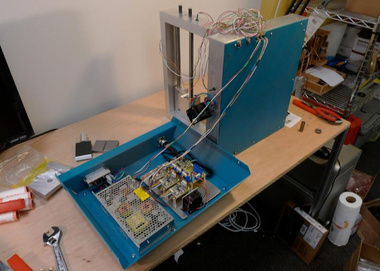
| All wired up! |
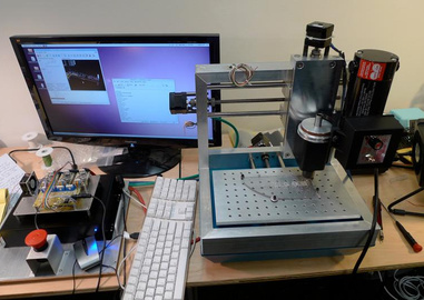
Driving around the machine for the first time on my workbench. |
|
| Due to noise issues, the switch was made to a LinuxCNC EMC2 based control system. |