|
 |
Configuration
Physical objects often display
some degree of regularity and organization. A fundamental
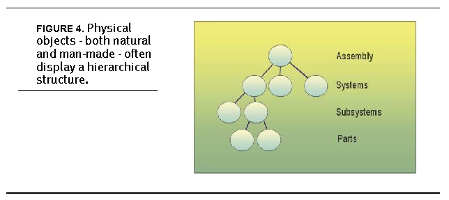
type of organizational structure is a hierarchy. We
think of machines having hierarchy - assemblies, systems,
subsystems and parts, as illustrated schematically
in Figure 4. Physical objects - both natural and man-made
- often display a hierarchical structure.. These hierarchical
descriptions apply not only to assemblies, but also
to aggregates and collections. A tea set, for example,
may be comprised of cups, saucers and spoons yet have
no physical connection.
Even
natural objects display hierarchy. Trees, being the
classic example, have roots, trunk, branches and leaves.
This characteristic of natural and man-made objects
to exhibit hierarchy is included in the Physical Markup
Language.
Beyond
simple containment, the relationship between components
is often critical in describing the physical system.
These relationships exist not only in the hierarchical
tree, but also among sibling elements. A mechanical
joint is a good example. Kinematic pairs, such as
revolute, prismatic and ball-in-socket joints, are
often used to describe the coupling between elements
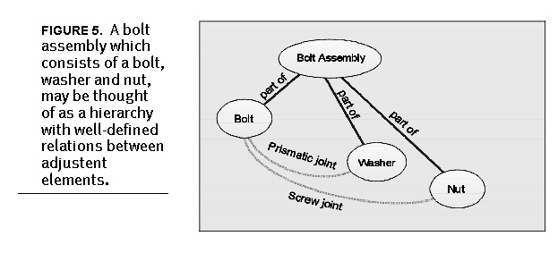
in a mechanical system. A bolt topology, illustrated
abstractly in Figure 5, A bolt assembly which consists
of a bolt, washer and nut, may be thought of as a
hierarchy with well-defined relations between adjustent
elements., shows how components are connected.
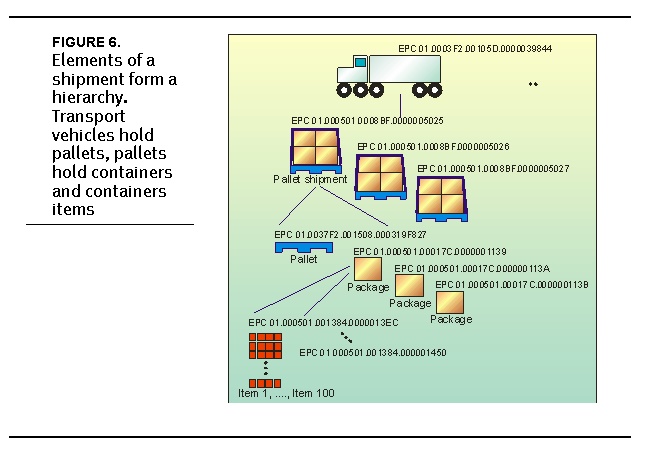
Elements
in the supply chain can also be thought of as assemblies.
A transport vehicle, pallet, container and item form
elements in a linked hierarchy, as shown in Figure
6, Elements of a shipment form a hierarchy. Transport
vehicles hold pallets, pallets hold containers and
containers items. In this case, we explicitly define
the pallet and pallet assembly as separate elements.
A pallet, for example, would be considered a discrete
item for a pallet logistics company, but a shipping
unit for a transport company. The Physical Markup
Language provides unambiguous descriptions for the
various potential users.
Even
individual products contain hierarchy. When you purchase
an item from the store, you may be actually buying
a group of products that were made at different times,
various locations and even by different manufacturers.
For example, you could purchase a razor handle by
itself, or the handle with four blades. You could
buy replacement blades in various configurations -
all with or without a handle - or you could buy a
promotional package that includes the handle, blades,
shaving cream and aftershave. Regardless of the configuration,
the handle and the blades are the same. The only difference
is their relationship to other objects. This relationship
of items is described by an object hierarchy. Since
many physical systems have this hierarchical structure,
PML captures this information.
To
describe a hierarchy, we use a common analogy of a
tree whose elements are arranged as branches and leaves.
A directory file system, ancestors and descendents
or a connected, acyclic graph are other ways to describe
the same concept.
For
this version of PML, we will not include cyclic graphs,
in which components eventually link to themselves.
Future versions may include a more general graph description
allowing more complex object relations and assemblies.
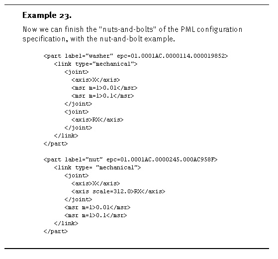
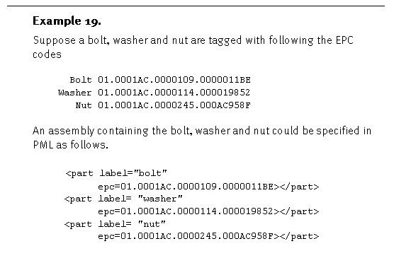
Part
We
introduce an element called a part
. The part
element includes an optional label
attribute, which is human-readable string identifying
the part, and an optional epc
attribute, which is the Electronic Product Code
of identifying part.
<part label=
string
epc=
xx.xxxxxxx.xxxxxx.xxxxxxxx
>
. . .
</part>
One
or more part
elements may be included in a PML file, each representing
a part of component of the physical object.
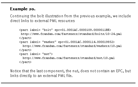
The
epc
attribute may be a virtual or a physically, but
in either case the EPC provides a link to an extenral
PML resource. The part
specification also allows links using the
usual Universal Resource Locator (URL) methods.
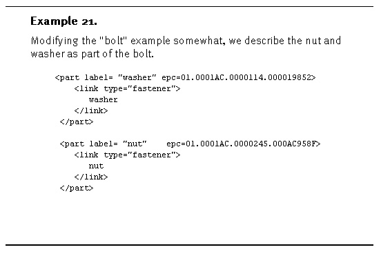
Link
The
part
component includes zero or more link
elements that describe how the part object is "linked"
to the parent object. In other words, some objects
are mechanically coupled, such as a nut and bolt,
and other are logically coupled, such as a tea service.
There
are some objects that have multiple linkages, logical,
physical, chemical, etc. The link
elements are intended to capture these relations.
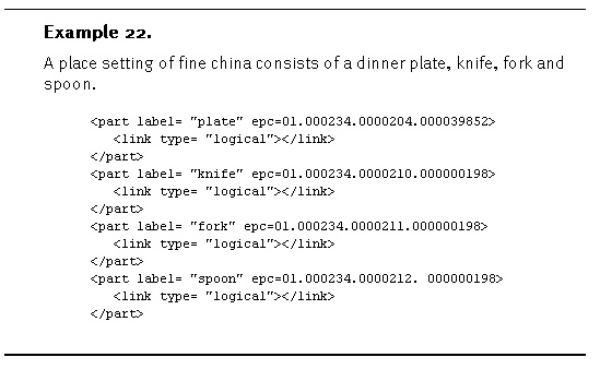
Each
link
element includes a type
attribute indicating the general type of linkage
- "logical", "physical", "mechanical",
"chemical", etc. The link
element also contains string used to describe the
particular linkage.
<part label=string
epc=xx.xxxxxxx.xxxxxx.xxxxxxxx>
<link type=string>
string
</link>
.
. .
<link type=string>
string
</link>
.
. .
</part>
It
is difficult - if not impossible - to classify all
the possible ways in which objects interact. Therefore
the type
attribute and contents of the link
element are, for the most part, unrestricted. This
version of PML, however, does provide some specific
link
types. These are logical
, physical
and mechanical
.
Logical
The
logical
type implies a conceptual link between components.
This may or may not have any physical realization.
The tea service, we mentioned earlier is a good
example of a logical
link.
Physical
The
physical
type implies a physical connection between the
objects. This physical association is not defined
explicitly within the specification, but implies
a generic physical coupling, such as "adhesion,"
"sewn," "woven," "attached,"
etc. The mechanical
type discussed in the following section, provides
a restrictive, but well-defined physical linkage.
Mechanical
The
mechanical
type defines a mechanical coupling between two
rigid bodies. If this link type is specified,
the part element contains a joint
element, which specifies the number and ranges
of a motions between the physical objects.
Mechanical
couplings between pairs of rigid, solid objects
are categorized into higher
and lower order pairs
depending on how the bodies are in contact. Lower
order pairs have a surface or planar contact,
such as a hinge or a screw, while higher order
pairs have a line or point contact, such as a
cam or a gear.
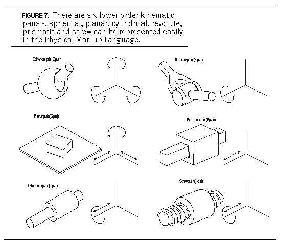
Within
lower order pairs there are six general types
of couplings - spherical, planar, cylindrical,
revolute, prismatic and screw, as shown in Figure
7, There are six lower order kinematic pairs -,
spherical, planar, cylindrical, revolute, prismatic
and screw can be represented easily in the Physical
Markup Language.
In
order to describe these mechanical couplings,
the link
element allows zero or more joint
elements. The joint
element includes one or more
axis elements, which contains a string indication
the axis along which the joint is free to move.
This string may be "X",
"Y", "Z", "RX",
"RY", "RZ," where
"X," "Y," and
"Z" are translations along those
respective axes and "RX,"
"RY" and "RZ,"
are rotations about the same.
If
more than one axis element
is included a scale attribute
must be set to a floating point value indicating
the degree of coupling between the two axes. In
other words, some joints, such as the screw joint,
couple movement between linear translation and
rotary motion. The degree of coupling is commonly
called pitch
.
<axis>[X,Y,Z,RX,RY,RZ]</axis>
<axis scale= float
>[X,Y,Z,RX,RY,RZ]</axis>
<axis scale= float
>[X,Y,Z,RX,RY,RZ]</axis>
<axis>[X,Y,Z,RX,RY,RZ]</axis>
<axis scale= float
>[X,Y,Z,RX,RY,RZ]</axis>
<axis scale= float
>[X,Y,Z,RX,RY,RZ]</axis>
Thus
the number of joint
elements determines the
degrees-of-freedom of the coupling between
the rigid, solid bodies.
Each
joint
element optionally includes a pair of msr
(measurement) elements, which represent the minimum
and maximum allowable range along those axes,
as well as an optional trans
(translation) element providing an arbitrary coordinate
transform between the object reference frames.
<link type="mechanical">
<joint>
<axis>[X,Y,Z,RX,RY,RZ]</axis>
<axis scale= float
>[X,Y,Z,RX,RY,RZ]</axis>
. . .
<axis scale= float
>[X,Y,Z,RX,RY,RZ]</axis>
<trans>
. . . </trans>
<msr> . . . </msr>
<msr> . . . </msr>
</joint>
. . .
<joint>
<axis>[X,Y,Z,RX,RY,RZ]</axis>
<axis scale= float
>[X,Y,Z,RX,RY,RZ]</axis>
.
. .
<axis scale= float
>[X,Y,Z,RX,RY,RZ]</axis>
<trans> . . . </trans>
<msr> . . . </msr>
<msr> . . . </msr>
</joint>
</link>
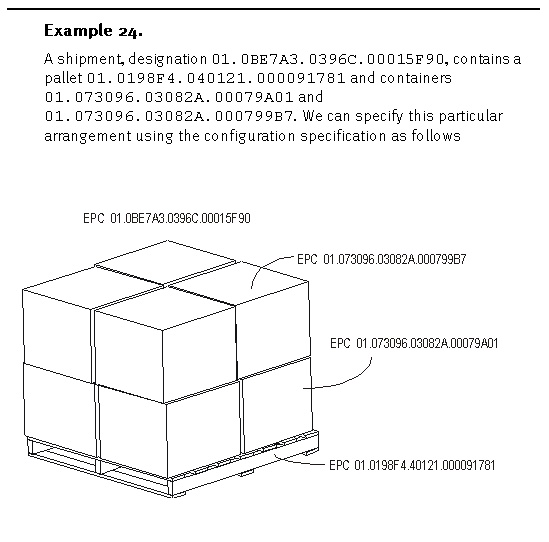
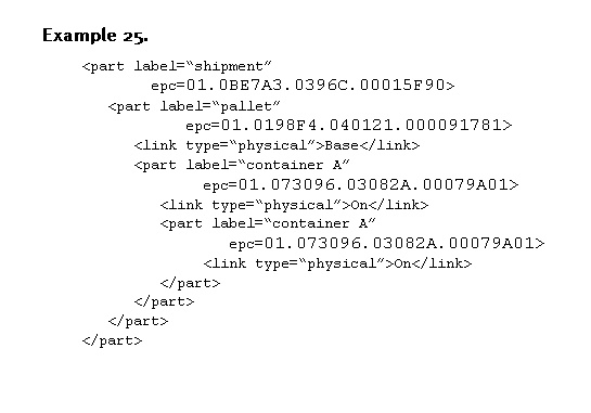
Hierarchy
The
part
element also optionally includes one ore more part
elements, thus defining a hierarchy of components
and subcomponents. We can use this to precisely
define assemblies, shipments, arrangements and general
physical configurations - both permanent and temporary.
<part
label=string
epc= xx.xxxxxxx.xxxxxx.xxxxxxxx
>
<link type= string
>
string
</link>
. . .
<link type= string
>
string
</link>
<part> . . . </part>
.
. .
<part> . . . </part>
</part>
. . .
<part label= string
epc= xx.xxxxxxx.xxxxxx.xxxxxxxx
>
. . .
</part>
<link type="logical"> string
</link>
<link type="physical"> string
</link>
<link type="mechanical">
<joint>
<axis>[X,Y,Z,RX,RY,RZ]</axis>
<axis scale= float
>[X,Y,Z,RX,RY,RZ]</axis>
. . .
<axis scale= float
>[X,Y,Z,RX,RY,RZ]</axis>
<trans> . . . </trans>
<msr> . . . </msr>
<msr> . . . </msr>
</joint>
. . .
<joint>
<axis>[X,Y,Z,RX,RY,RZ]</axis>
<axis scale= float
>[X,Y,Z,RX,RY,RZ]</axis>
. . .
<axis scale= float
>[X,Y,Z,RX,RY,RZ]</axis>
<trans> . . . </trans>
<msr> . . . </msr>
<msr> . . . </msr>
</joint>
</link>
</part>
|
|
|
| |
|
|
|
|
|
|