The design details for the Ultraluminous Illuminator are saved below for posterity, as much of the information is relevant to the Light Brick as well. I am personally focusing on the Light Brick for the time being as I can really only manage one LED project at a time while taking care of my day job.
In particular, the sections below covering the LM3404, the best LED power supply chip on earth, are copied wholesale into the design of the Light Brick with limited modification. However, there are some interesting changes to the Light Brick design intended to make it more robust.
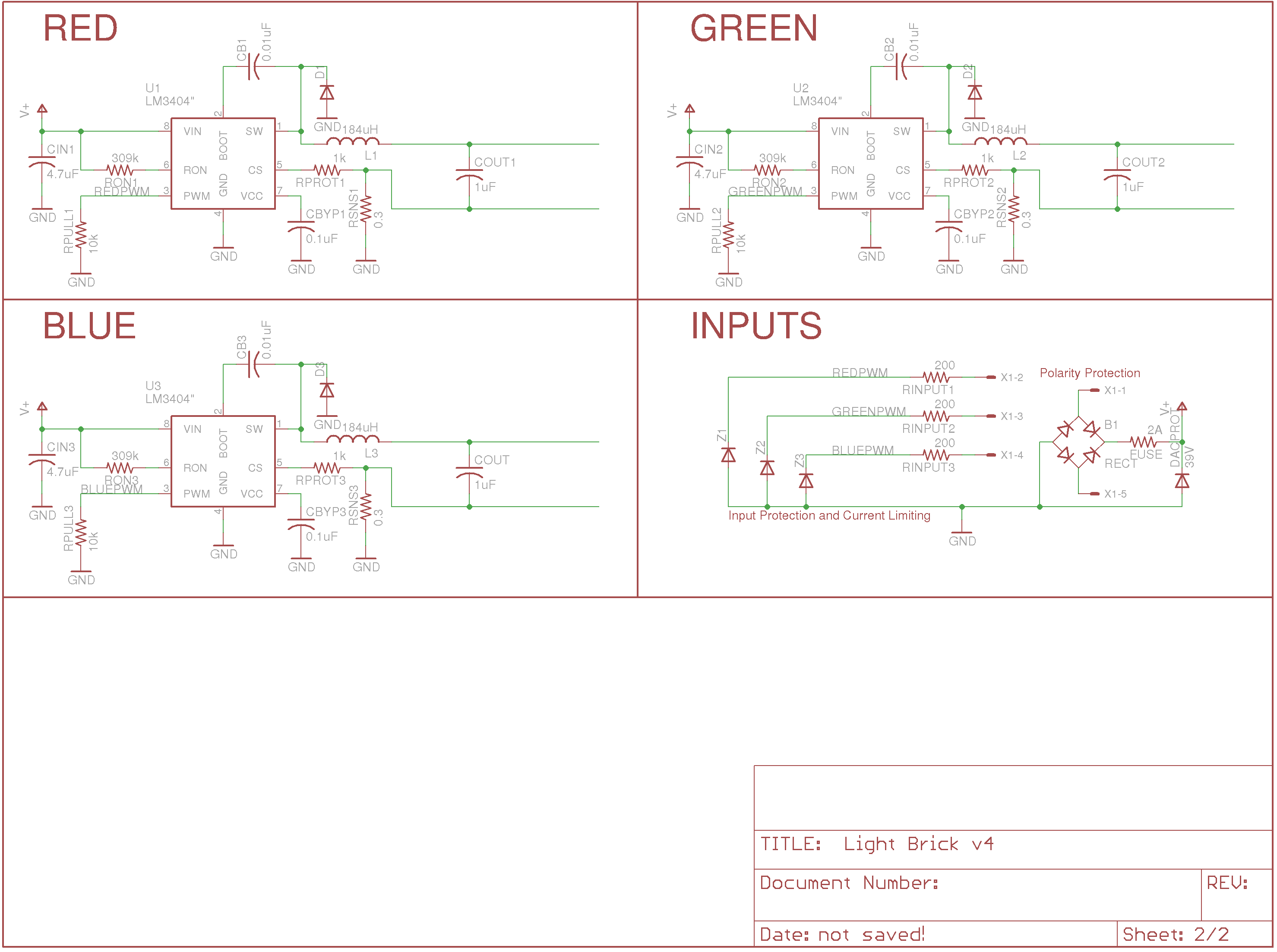
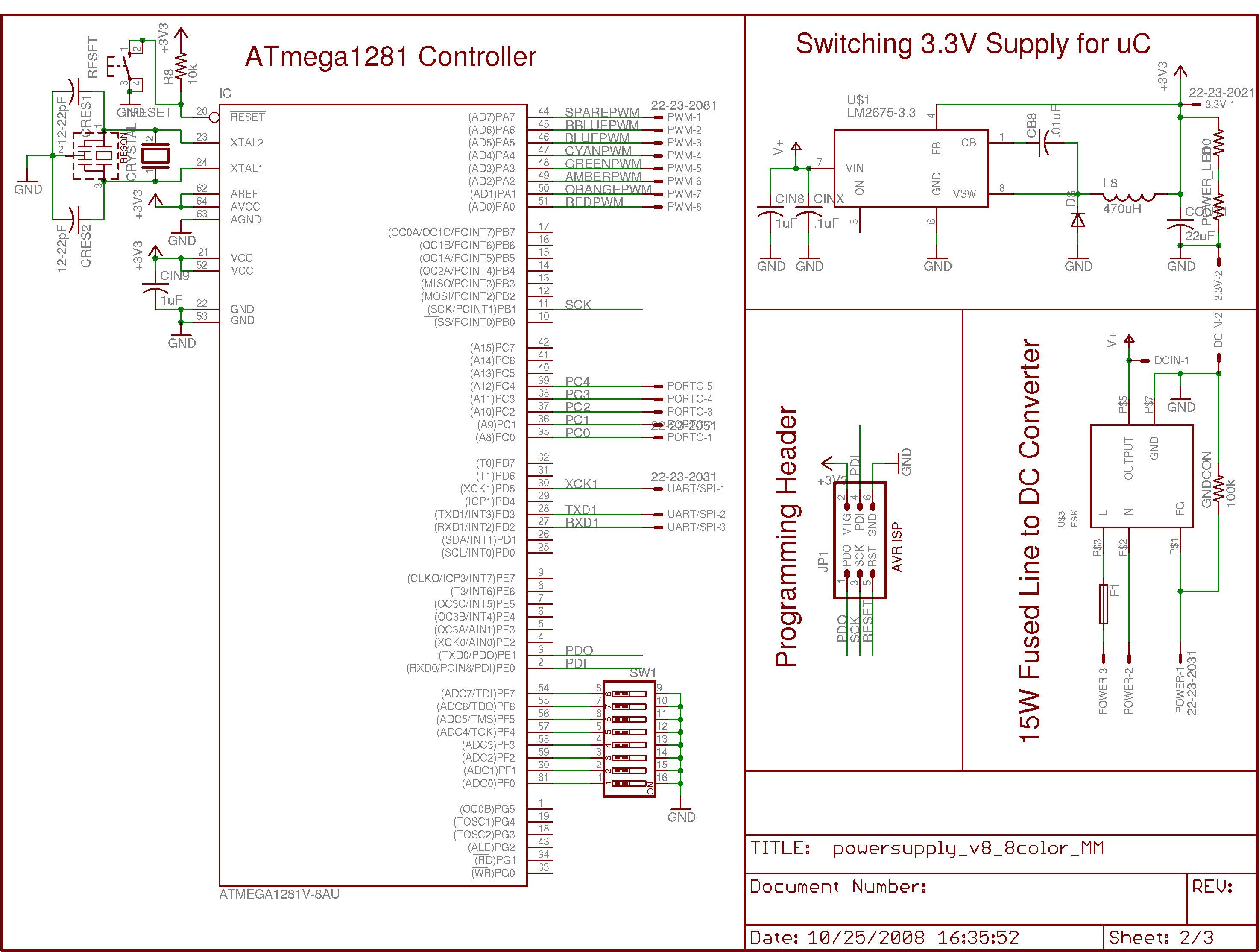
Because the Light Brick now has the separation between user and device at a different location than the Ultraluminous Illuminator, it was important to add additional protection, both for the user and for the devices. A copy of the new schematic is shown below.
In this schematic, you can see that I have added input protection resistors of 1k in order to prevent spikes in the voltage on the digital input lines from breaking the power supply chips. Additionally, there is a zener clamping diode of 5.6V across the pulldown resistor in order to prevent the voltage seen at the DIM pin of the LM3404 from going over 5.6V. Next, you can see that there is a 2A surface mount fuse and 39V zener diode attached across V+ and GND in order to prevent the user from damaging the board by accidentally attaching the system to too high of a voltage (say, line voltage). They'd have to replace the SMT fuse, but that's a lot easier than replacing four SOIC-8 power supply chips. Last, I added a full bridge rectifier across the power inputs so that if the power plus is attached backwards the chips don't see a large negative voltage (which would likely damage them).
The end result is a system which should be robust enough that it will survive any number of typical errors encountered with these sorts of systems. Plugging in the power cable backwards will result in nothing more than the red and blue channels being switched. Putting line voltage across the power pins will hopefully just result in a blown fuse instead of a totally destroyed board. Even putting line voltage across the digital control pins might not immediately destroy the board -- it would probably survive until the zener protection diode burns out and stops shorting the excess voltage.
The new version (v9) of the power supply and LED board are based heavily on the old versions, so I have left the old versions up on the website to draw from. These are the main changes:
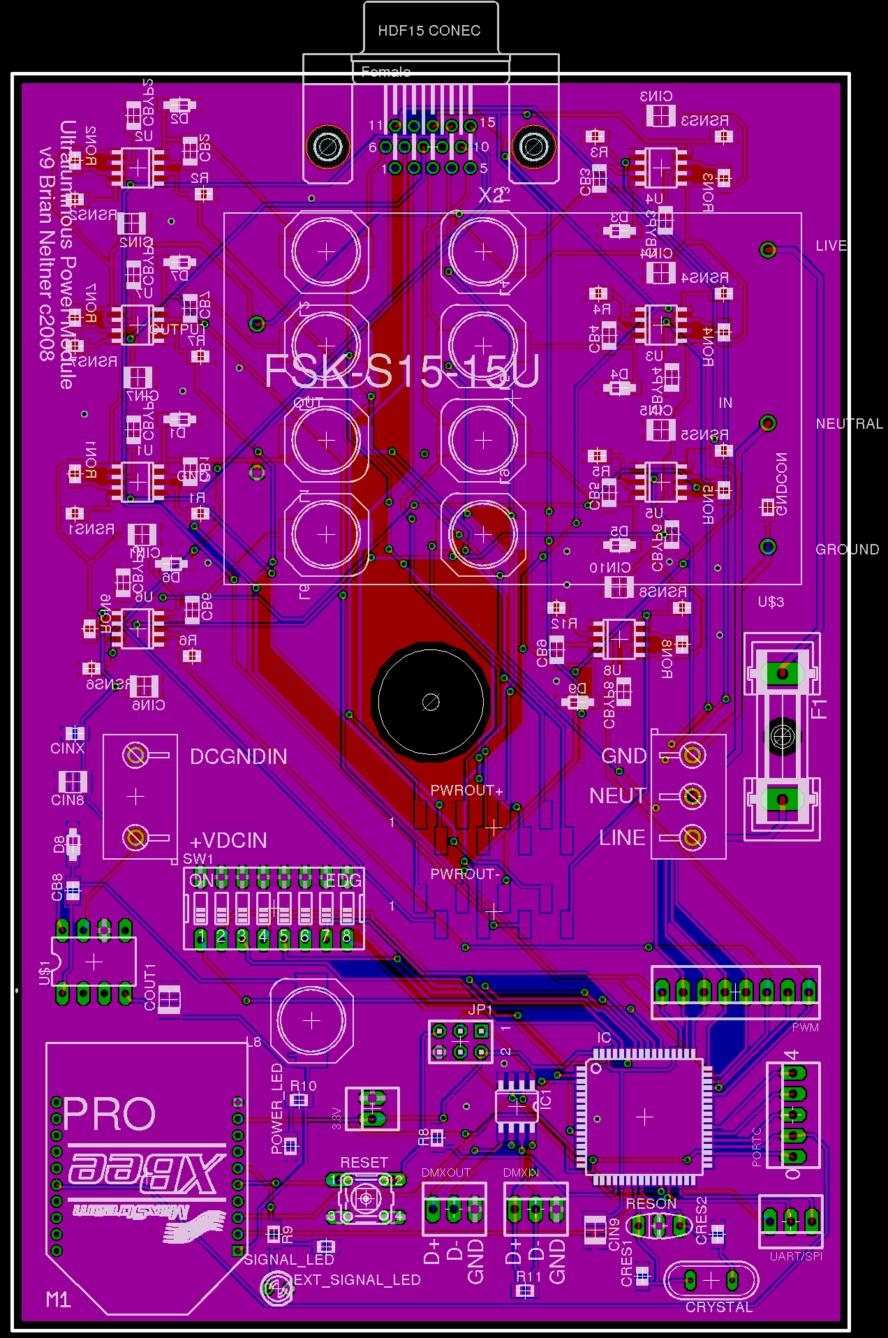
I chose to switch to the Atmega1281 processor because I was tired of needing to boot into windows in order to program the system. I am also learning how bootloaders work with the intent of setting it up so that I can reprogram the firmware over Zigbee wireless. I had some issues getting this chip to run stable which I finally narrowed down to an unstable oscillator. I had been using an internally compensated ceramic resonator (Murata CSTLS8M00G53-B0), but when I switched to a crystal oscillator with external capacitors for stability, all of my problems went away. I'm also now running the entire system on 3.3V instead of 5V so that it can cleanly interface with the Xbee Zigbee interface chip. I accomplished this by using the LM2675-3.3, a closely related chip to the regulator I was using originally.
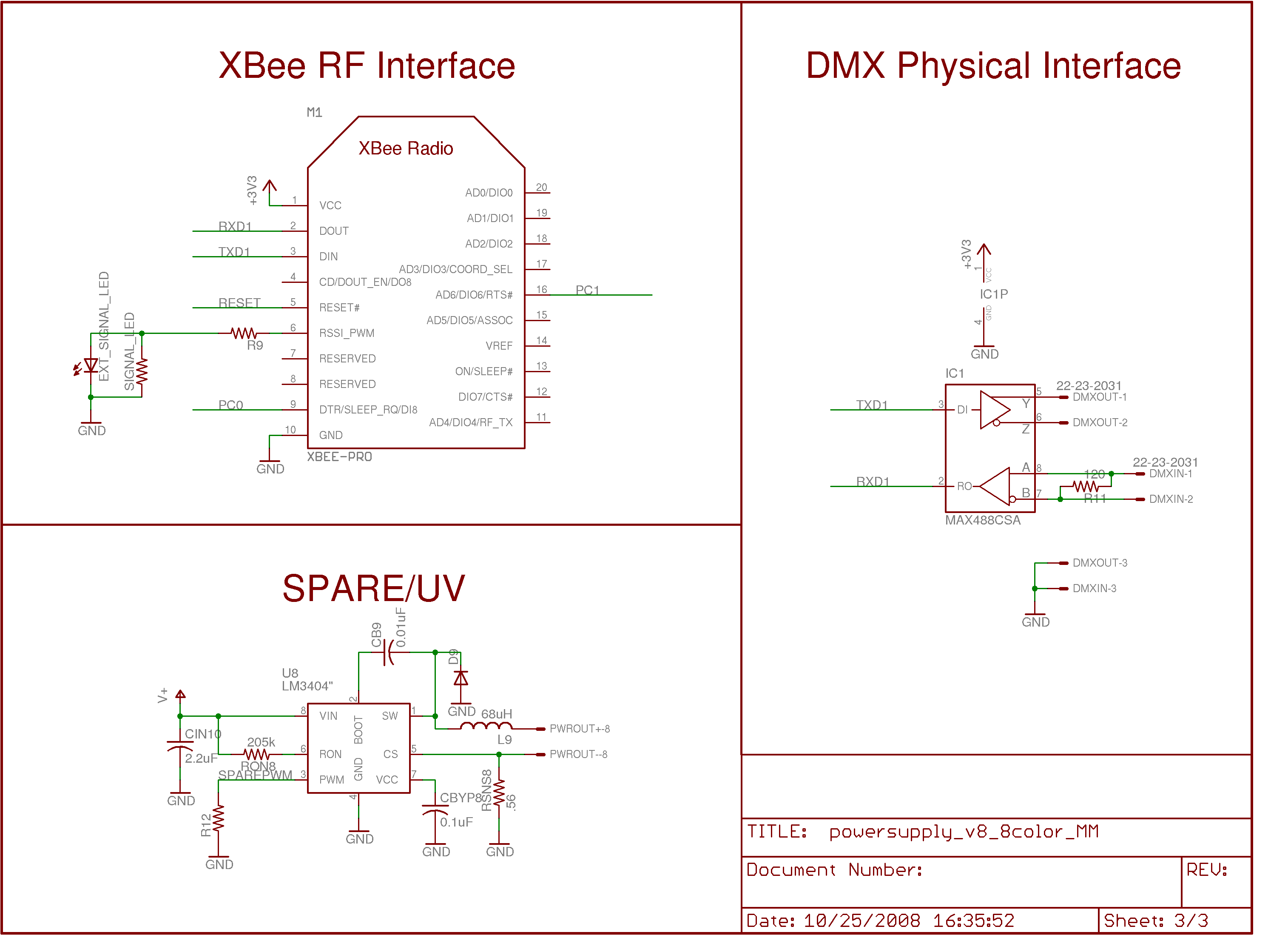
I wanted to be able to permanently install a light on a wall while retaining the ability to control it remotely. By far the best solution I found for this was to use the Xbee RF Module, a great chip which lets you convert a system that would normally communicate over USART into one that talks over Zigbee transparently. You can also do more advanced things like give RF modules addresses, use mesh networking, and use guaranteed delivery, but for now I'm just using transparent USART mode. Best of all, the chip is only about $20. I'm using the one with a wire whip antenna, which I stick out the side of my aluminum case through a small hole.
I found this great hollow gooseneck support from Moffatt which is wonderful. I left on the HD15 connectors in case I want to have a more portable "light stick" with power coming out of the end, but also put on SMT Molex male header pins so that I can run ribbon cable through the gooseneck and connect to the middle of the board instead of the end. It looks really good to do it this way, but be sure that you get plugs which are spec'd for the gauge wire you use. In my case, I used the Molex 68301-1019 for the SMT header, and the Tyco 3-640622-8 26AWG Connector
I found the FSK-S15-24U, a great little 15W 24VDC power supply that fits perfectly inside the case and solders directly into my board. I used screw terminals for Live, Neutral, and Ground, and put on a fuse to protect the power supply. I also put on screw terminals for +24V and GND so that I can run a low voltage DC line common to all lights and then only have to buy one larger power supply. Each little brick costs about $60, so in an installation with many lights, it's definitely preferable to use a central supply. I'm using a Meanwell SE-600-24, a 600W power supply, to run the lights in my gallery now.
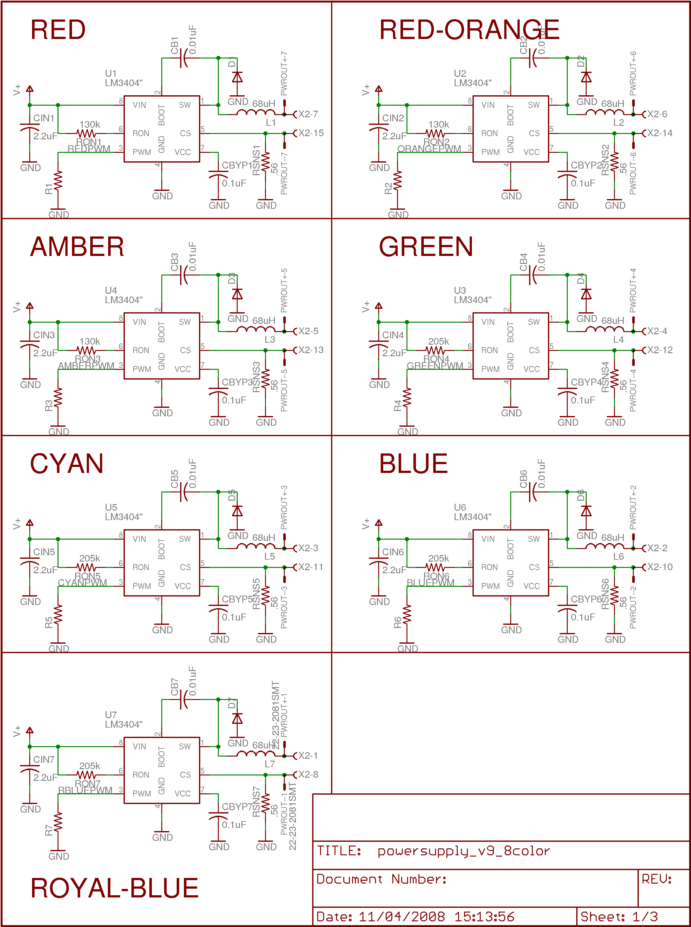
I switched from 4+1 channels with 7 LEDs per channel plus 2UV to 7 channels of 4 LEDs each plus one channel of 2 UV, all at 350mA instead of 500-700. I had one of my Rebel LEDs burn out, and the brightness is so high already that even at half the current with half as many LEDs, the lights still leave nothing to be desired for my particular application. Of course, I could run them at 700mA instead, but I'd rather they run cool and forever than run twice as bright (for now). Plus, it balances better with the UV LEDs now.
The diffuser did a fine job of protecting viewers from the UV LEDs, but I am worried that if the cover were to come off someone could hurt their eyes. To deal with this, I purchased clear acrylic adhesive, and suspended very find silica (sand) powder in it to scatter the light. Putting a big blob of this over each UV LED (oh... each $60 LED... it pained me to do this) resulted in what looks to be a pretty much permanent diffuser over each one. These would not be easy to remove, and are unlikely to fall off. Of course, I am not suggesting that these LEDs are now safe, just that I am now comfortable using them in my own home, under my own supervision.
Just in case I want to implement it someday, I included a place to solder on an RS485 transceiver, which would be the first step in implementing DMX.
I put in an 8-switch DIP switch in case I want to let a user set a variable (like device address or default mode) physically instead of through reprogramming or sending commands with the Zigbee interface.
Here are new Schematics and Layouts for the current version.
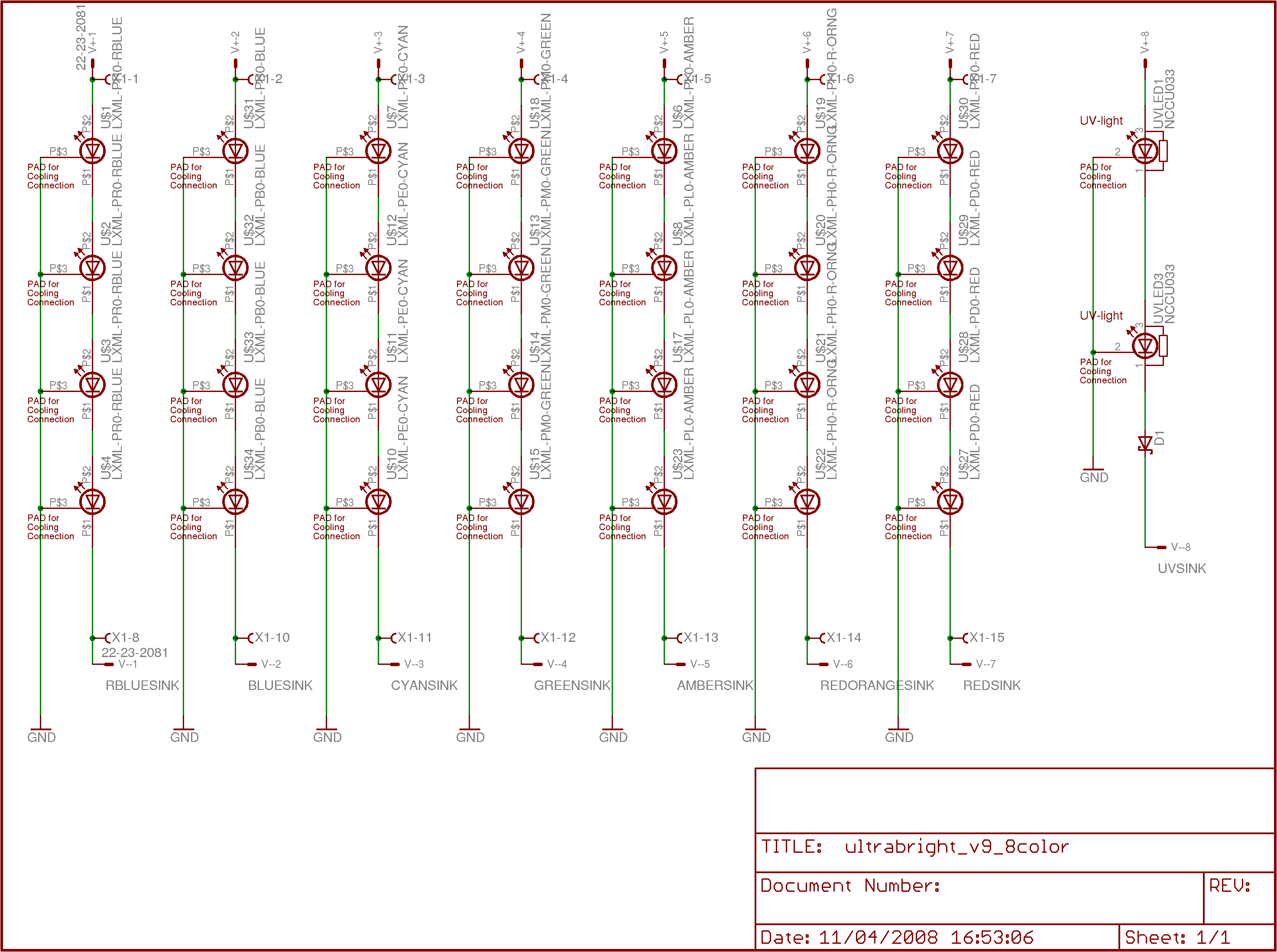
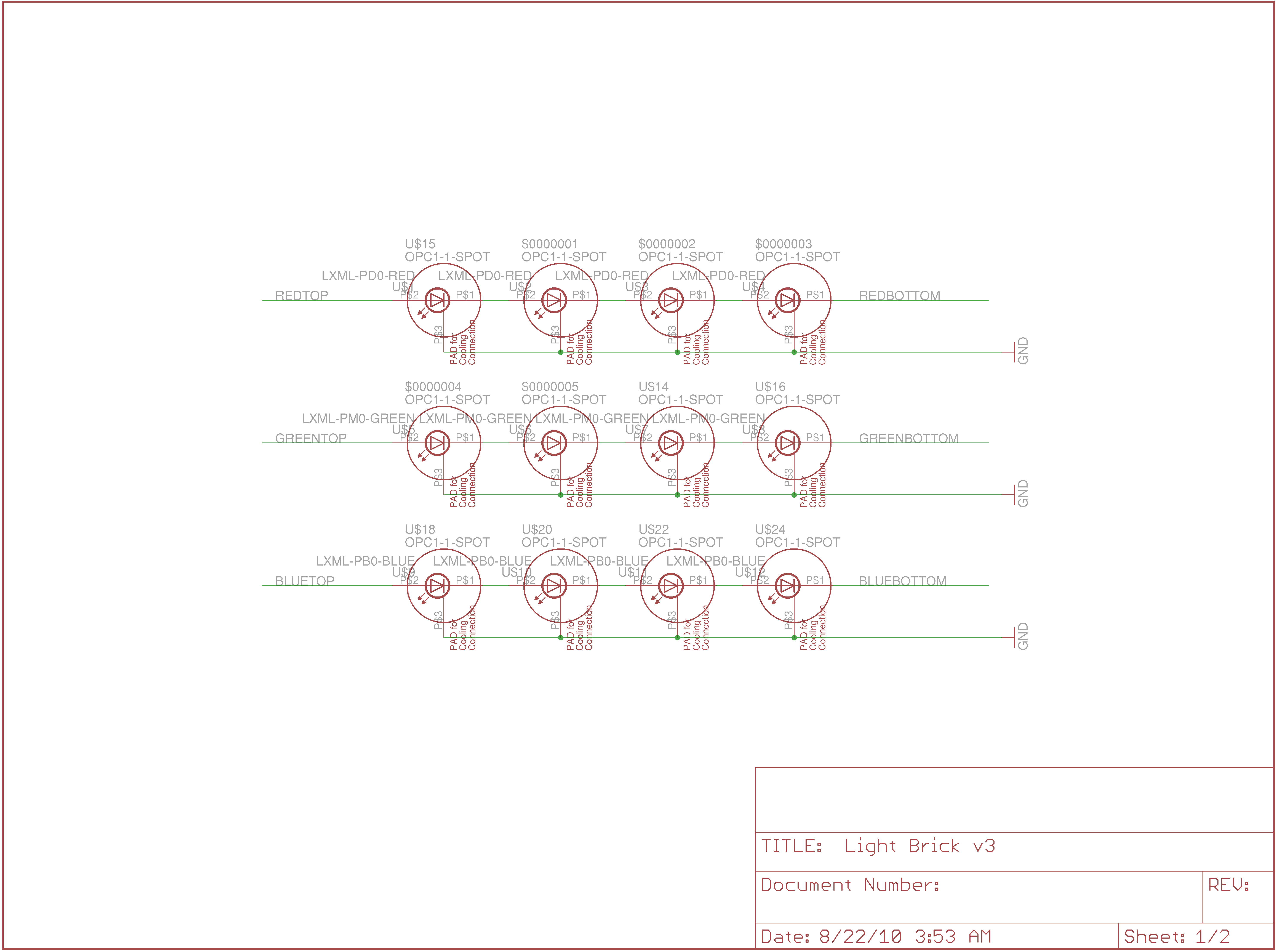
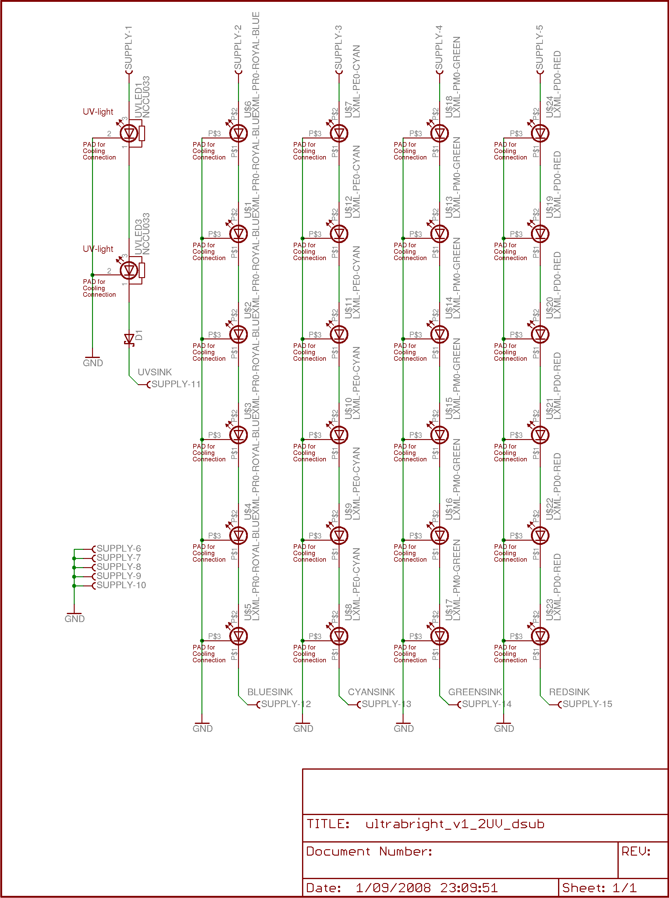
This design uses 6 each of the state-of-the-art Luxeon Rebel LEDs in whatever four colors are desired (I used red, green, cyan, and royal blue), along with two NCSU034A Nichia UV LEDs to produce the light output. Both of these LEDs are particularly nice because their heat sinks are not electrically connected to the die like some older Luxeon LEDs were. This means I can have a single heat plane to remove heat from the LED die instead of needing to electrically isolate every single LED's heat sink plane from every other.
As a word of warning, the NCSU034A LEDs output over 300mW of UV light at 385nm! This is a LOT! What makes them especially dangerous is that the die is only a millimeter or two on a side, so the angular intensity of the light is extremely high. Do *NOT* turn these on in an environment where anyone can look directly at them. They are extremely dangerous to the eye, and you will have a *permanent* blind spot if you look directly at them. To make them safe, I used polyethylene plastic sandwiching a Luminit Holographic Light Shaping Diffuser (LSD... yeah, I know, they came up with the acronym first) an inch and a half away from the board to make the apparent source size over an inch in diameter. This decreases the angular intensity from the class 3b level to the class 1 level. I am not liable if you blind yourself by using these LEDs! Seriously, don't fuck around with these.
Funny story that. Every time I tell an MIT student that the UV LEDs will permanently blind them if they remove the cover, the response is the same. First, they say "Really?", and then they attempt to look into the endcap. True story. Explains a lot, I think.
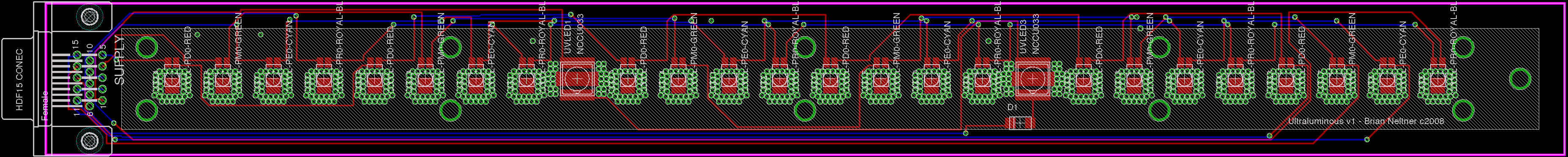
Anyway, I used a hot plate and some heat channeling tricks in the thermal plane to effectively solder the Luxeon Rebel LEDs to the boards I printed (they're a bit of a pain to solder by hand). I chose to use a monitor connector for the power connector because each pin is able to carry up to 3A without a problem. Each channel of LEDs draws 700mA, so a typical header is really pushing the limits. A nice side effect is that the cable assemblies and connectors are very readily available and are pretty cheap.
Due to the large expense of the actual LEDs, I chose to separate the power supply from the LED board so that if the power supply had errors, I could correct them without remaking the LED board as well. This also makes things much more modular overall, so I think it was the correct choice. The end result is that the LED board only actually has LEDs and a single protection diode to prevent against somehow plugging the supply in backwards (unlikely with a chiral connector like the HD15, but better safe than sorry with $180 worth of UV LEDs). The back of the board has the soldermask removed with no traces so that it can be directly screwed down into an aluminum chassis to act as a heat sink. Additionally, thermal vias were placed near the heat sink to let heat move from the LED die to the back of the board.
The actual chassis is a 1.5"x1.5" U-channel of aluminum with a 1/8" wall thickness. I milled a slot into each side so that I could slide the sandwiched polyethylene/LSD into the slot to form a difficult to remove and professional-looking cover. I then milled two end caps out of ABS plastic to prevent MIT students from looking in the ends in an attempt to blind themselves.
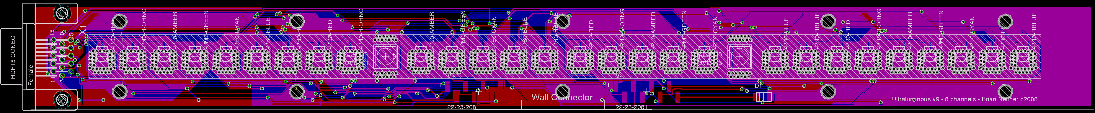
Note that both of the above images are shrunk, not low-quality. Just click on them to view the unscaled version in your browser. If you would like eagle schematics and board layouts for this, please contact me. I only make images readily downloadable so that I have some (illusion of?) control over who gets them (I'm looking at you, China). Not that they're particularly tricky, I just would like to have an idea of who is using my designs. The designs are copyrighted (anyone may use them for non-commercial use), but I have no particular desire to patent any aspect of the design (the state of LED light fixture patents being rather absurd enough already).
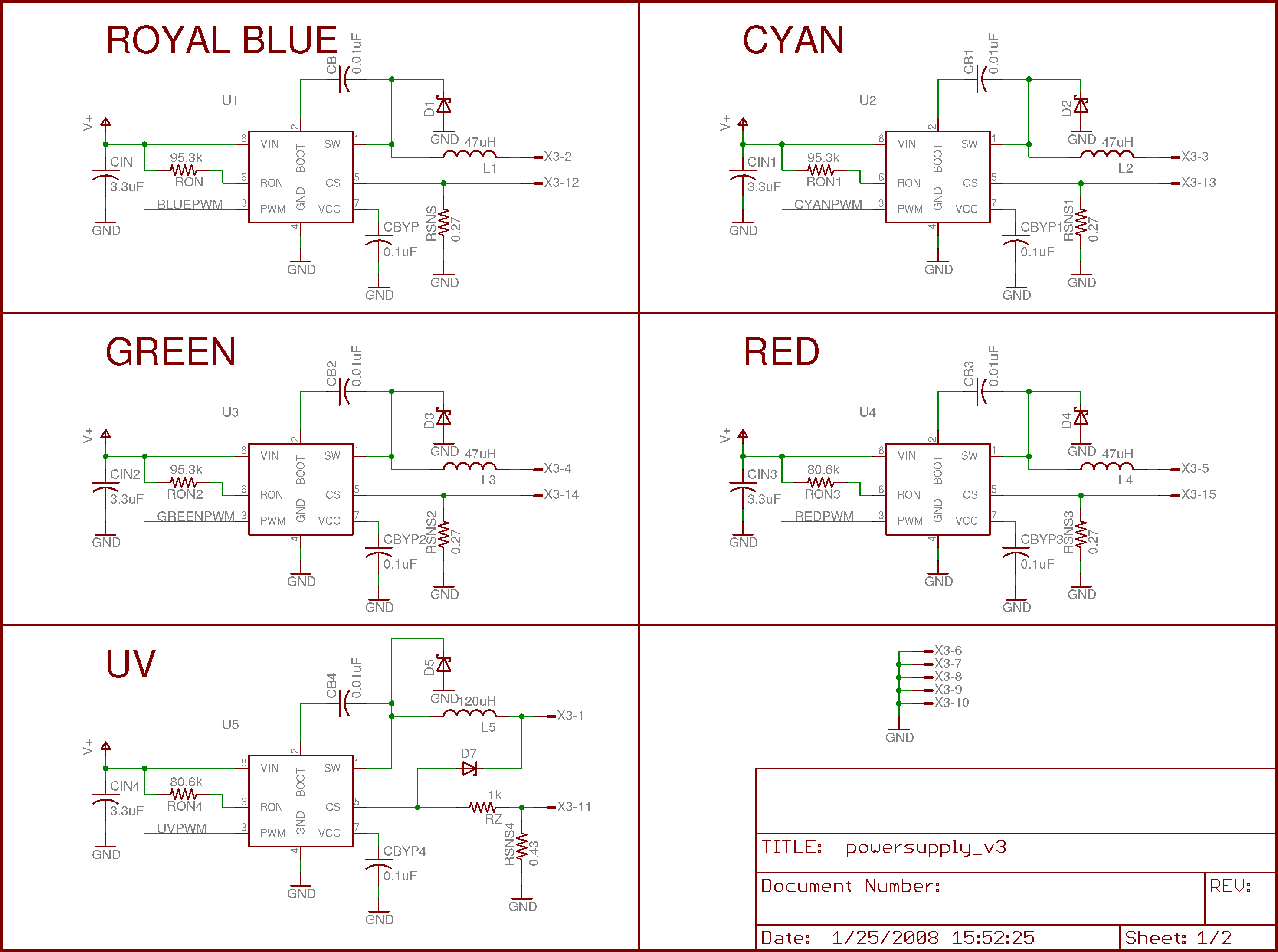
Power is one of the trickiest parts of building a high-quality and reliability LED system. First, LEDs want to be operated in "constant current" mode, and the brightness is usually controlled by current, not voltage. Additionally, on the types of high powered LEDs used in this project, the forward voltage can vary by up to a volt between the minimum and maximum specified. When operating a series of 6 LEDs, this adds up to provide a fair amount of uncertainty in the total forward voltage.
For instance, the Royal Blue Luxeon Rebels have a nominal forward voltage of 3.15V, but can vary between 2.55 and 3.99V. That means that the actual voltage drop could be anywhere between 15.3V and 23.94V, and the power supply needs to be able to handle that range while providing a constant 700mA. Further, LED brightness should be controlled using PWM or byte encoding at a high frequency to achieve the highest efficiencies. Efficiency may seem like a silly thing to worry about in an LED fixture, but there are serious problems which arise from generating heat on the board -- the LEDs can only withstand temperatures of 130C, so it is critical to make sure that light generation is as efficient as possible.
The best part I have found for doing this sort of power regulation and supply is the LM3404 from National Semiconductor. This is a current feedback buck converter (switching regulator) with up to a 70V input voltage and 1A of output current with internal transistors, so it is relatively easy to get 85%+ efficiency on the current source with a minimum of external components. Other designs will use a current mirror or source built out of discrete transistors and using linear regulation -- these will typically be much, much less efficient than the LM3404.
The converter essentially works by closing a switch to put the input voltage on the output. After the LED load, the current goes through a "sense resistor" before going to ground. The current will dictate the voltage across the sense resistor according to V=IR, and that voltage is compared to an internal reference. If the voltage is too low, the current is also too low, so the voltage output switches on. If the voltage is too high, the current is also too high, so the voltage output switches off. In this way, a very simple infinite proportional gain feedback system is built that provides a current set by the value of the sense resistor to the load, regardless of the input voltage.
The LM3404 is also great in that it provides a PWM port. When the pin is pulled low, the current output stops, and when you set it high, the current output turns back on. This allows me to turn the LED on and off extremely quickly in order to change the apparent brightness.
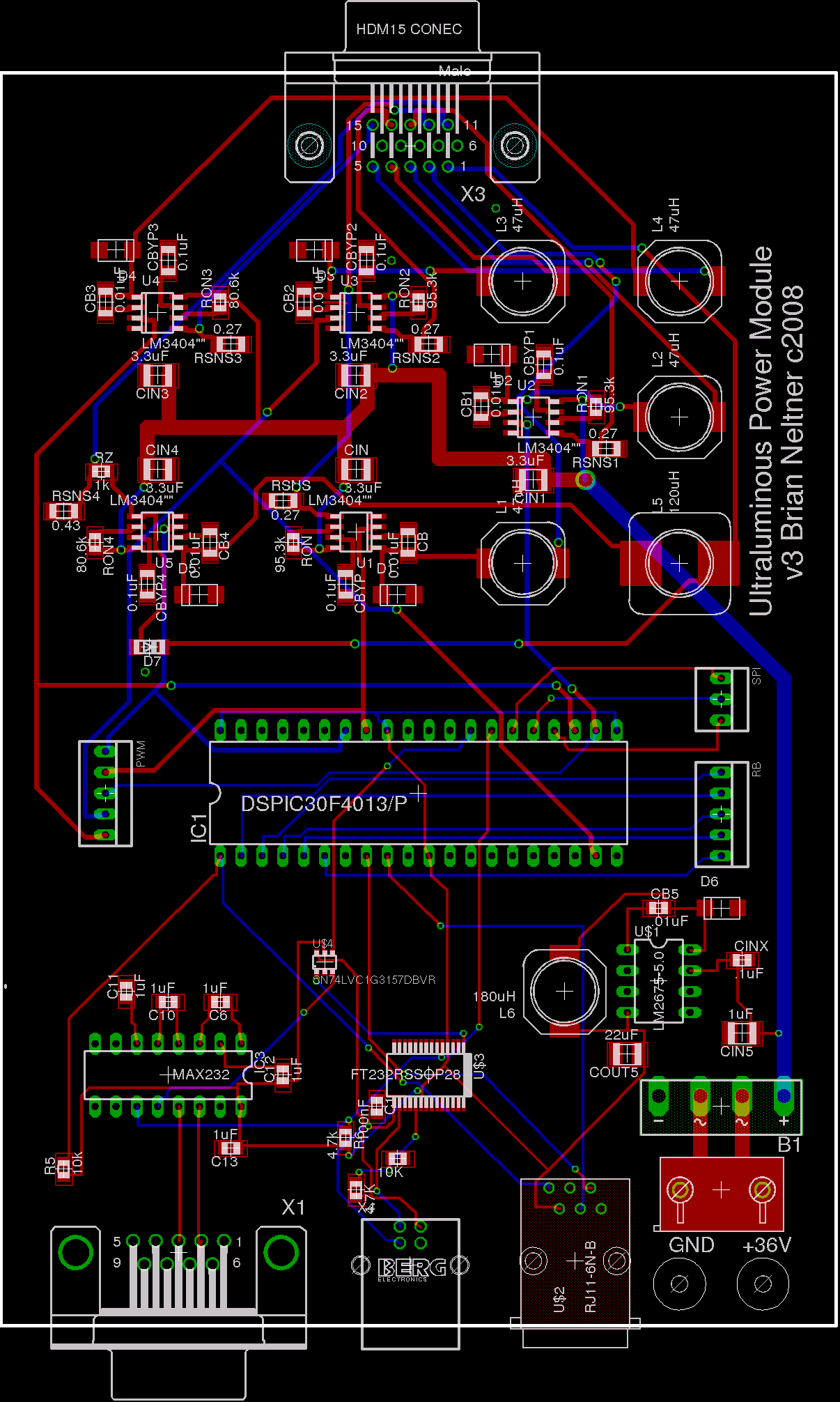
The PWM ports are, in turn, controlled by a Microchip dsPIC30F4013. There is no particular reason why this chip is special, it's just one that I've used in a lot of projects. It has 5 independent 16-bit timers, which makes writing PWM routines trivial. Additionally, it supports many interrupt levels (unlike the Atmega parts), so support is less complicated. I'm not much of a programmer, so the more I can buy built into the chip, the better.
I included a RS232 connection as well as a USB port so that when I get around to finishing it, I can set the device up to be reprogrammed without changing the actual software. The idea is that the user will draw out a pattern on the chromaticity diagram using a java applet on their computer, it will compile into a script, and download the script into the EEPROM on the dsPIC. From then on, when the light is turned on, it will boot up into the last programmed color sequence.
I also left the three SPI pins free so that when I get around to it I will be able to interface the dsPIC with a wireless communication chip using Bluetooth, Zigbee, or perhaps even 802.11 so that computer configuration files can be uploaded without even needing a cable. Doing it that way will make permanent installations a heck of a lot nicer to administer. If you happen to be good with wireless protocols and might be interested in helping me design that part of the system, please feel free to contact me. I'm always looking for a good collaborator to design with (and potentially go into business with if it works out well).
There's a 5V switching regulator, the LM2675-5.0, also from National Semiconductor, which supplies the digital components in the circuit. The idea of linearly regulating 36V to 5V with the 14% efficiency that entails, was unattractive at best.
Finally, after some unfortunate incidents with designs that weren't properly protected against user error, I put a full bridge rectifier on the (nominally) 36V DC power input. This way, the user can connect the positive to either input without damaging the device (in fact, it will run regardless of how it's plugged in).

Again, please note that the above are high quality images scaled down for display in this file. Just click on the images to view them unscaled. Also, if you would like to get eagle files for the power supply, just contact me and I will send you a copy.
If you are interested in doing LED based art and are looking for advice, are interested in having me build you a custom built LED light fixture of either the color brick or the Ultraluminous Illuminator (with whatever colors you want to use installed and preprogrammed), or doing a collaboration (Boulder, Boston, and Bay area only, please) with me, please contact me by sending me an email at neltnerb@led-artwork.com. I'll have to work out the legal issues associated with providing LED lights first, but I believe this just entails paying 5% of the proceeds to Phillips for the using their intellectual property and probably having you sign your eyes away in the case of a UV equipped light.
