This is my latest project, with the first working prototype constructed on July 23, 2010. The goal here is to design a modular, ultrabright system suitable for any hobbyist to build their own LED lighting system based on any control scheme they like, for cheap, and without having to know power electronics or fabricate their own PCB. This should allow enough flexibility for someone to control the system using anything from an arduino board, to a parallel port on a computer, to an entirely custom designed system.
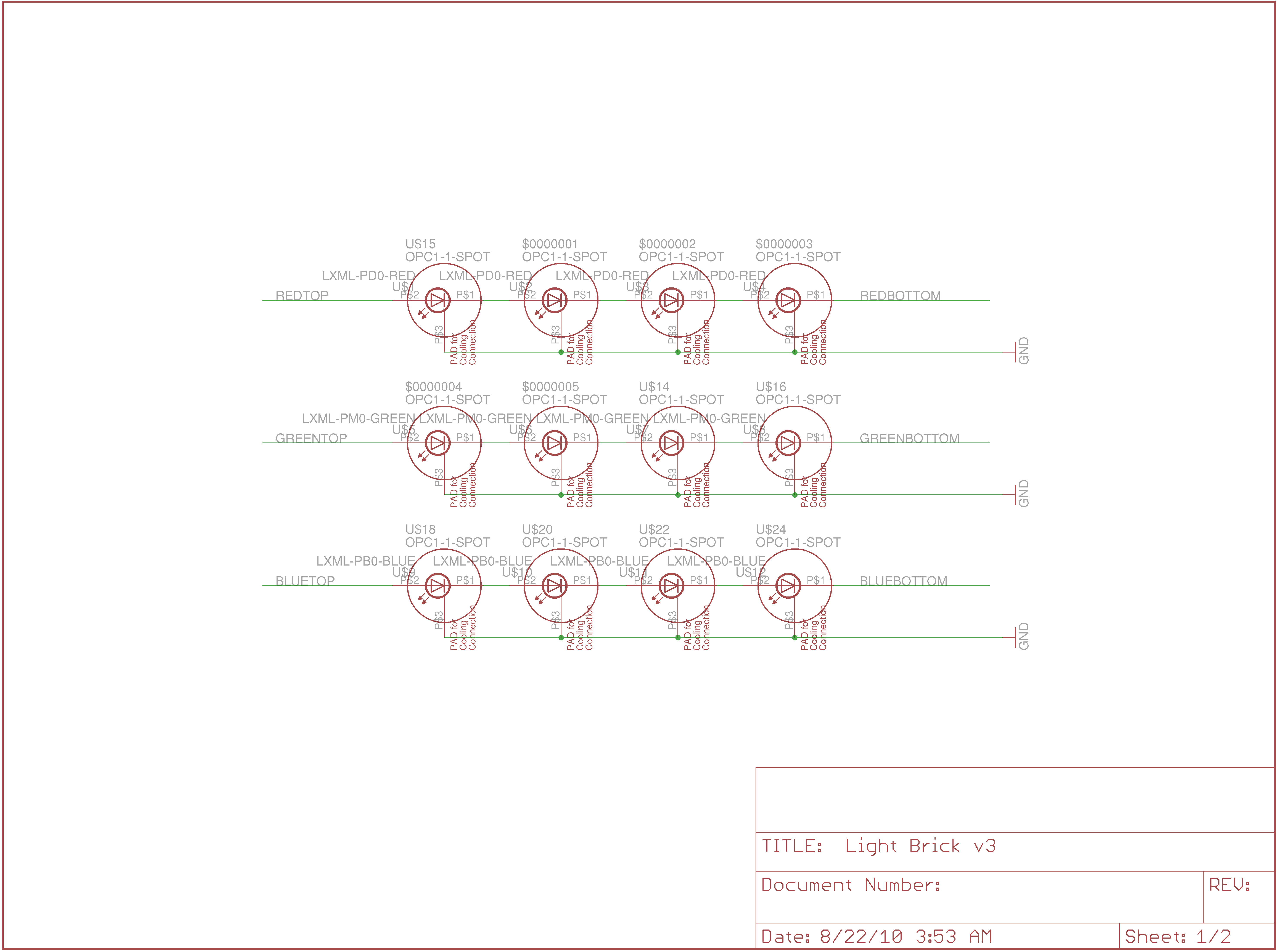
The basic design is fundamentally very similar to the Ultraluminous Illuminator in that it uses the same design for the power circuitry. A National Semiconductor LM3404 is used as the basis of the power circuitry with a buck converter in order to provide a constant 700mA regardles of input power voltage (18-36VDC). The board has three colors of LED -- red, green, and blue Rebel Luxeons from Philips Lumiled, with four of each color LED per board. Each control pin is pulled down to ground so that the device defaults to "off", and connected to a five pin connector for external control.
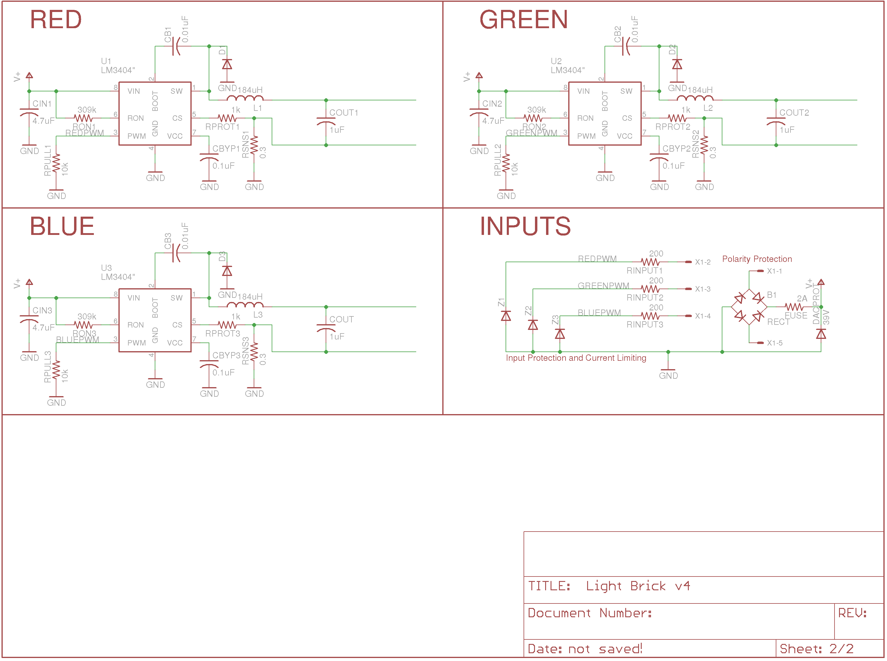
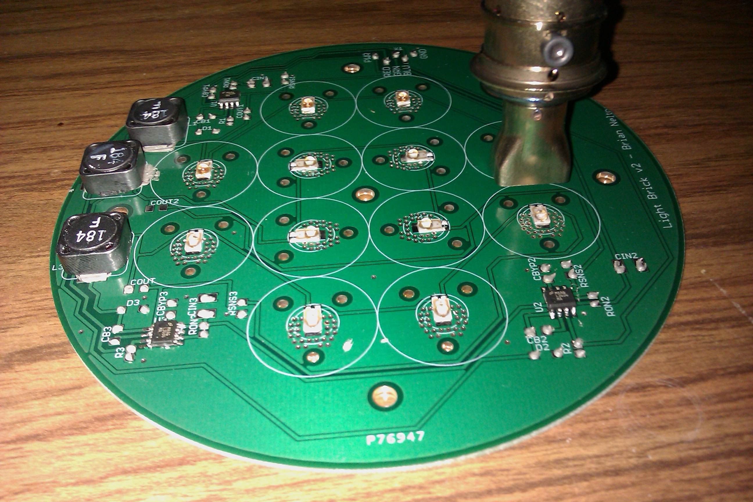
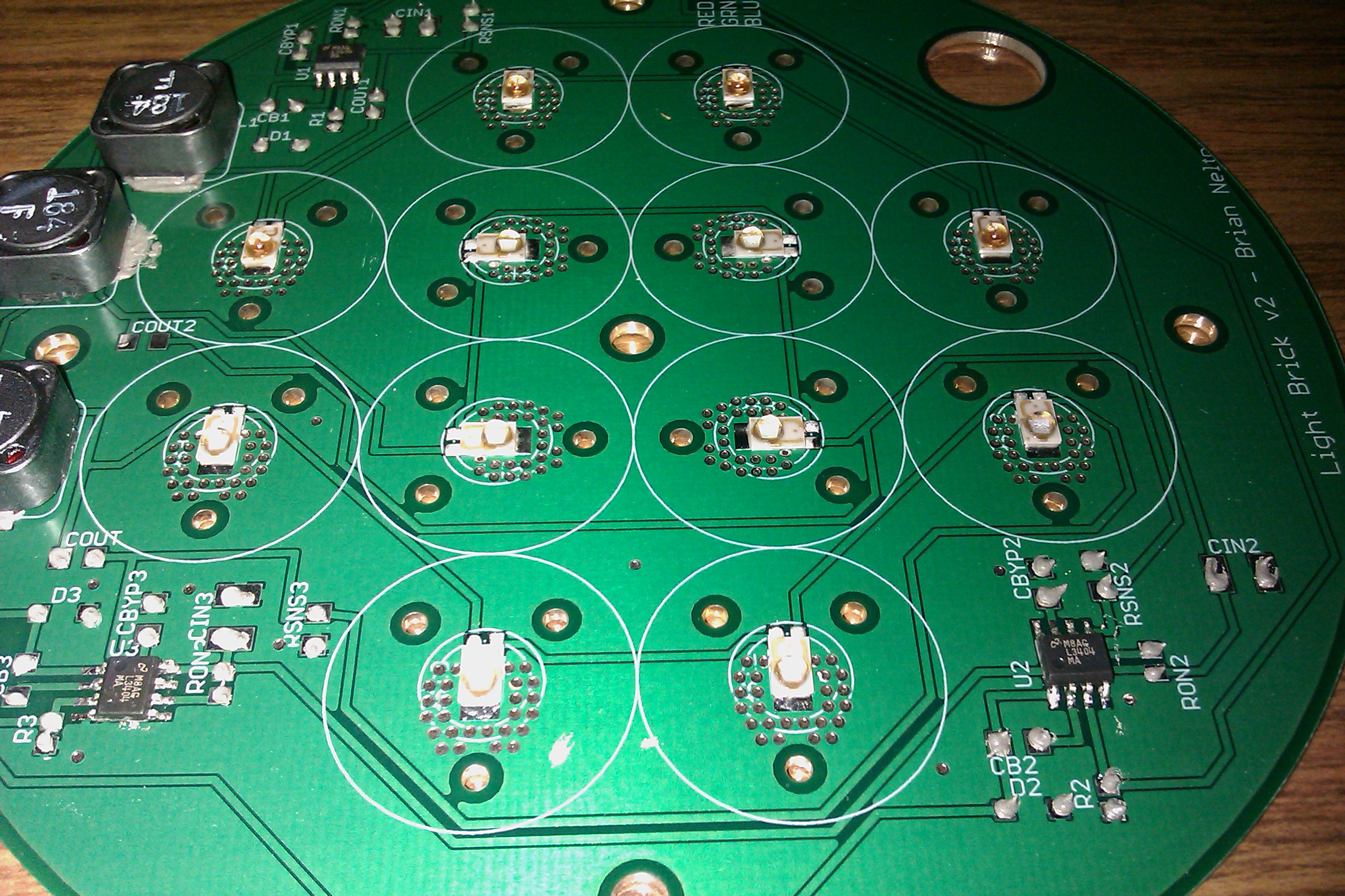
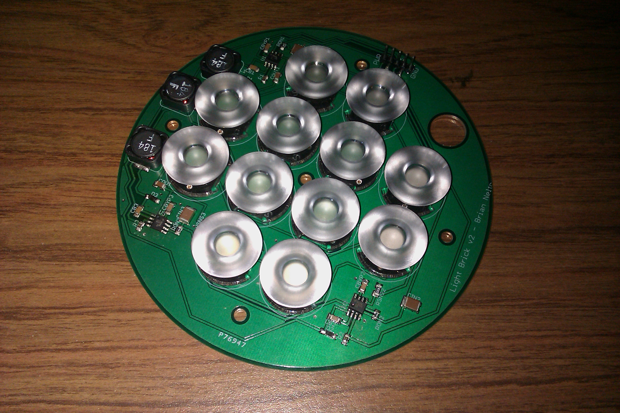
As you can see, the schematics are fairly simple, limiting the ways the device should be able to fail! The LED board layout (below) is designed so that the blue and red LEDs are on opposite sides of the pattern with four green LEDs in the middle. This layout allows for me to put every single electrical trace on the PCB in a single layer (with a lot of effort!), and by using only SMT components, the back of the board is entirely bare of electrical contacts.
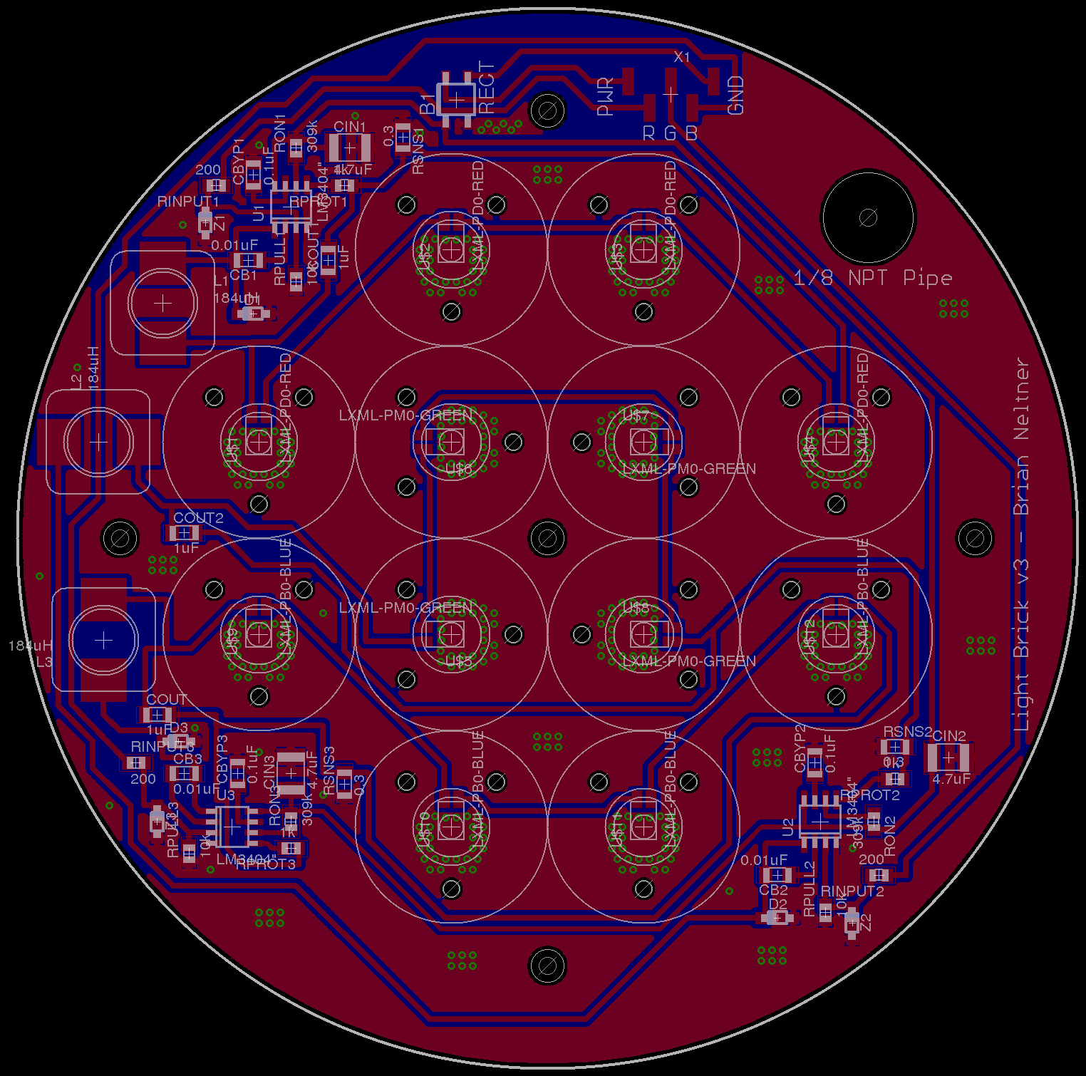
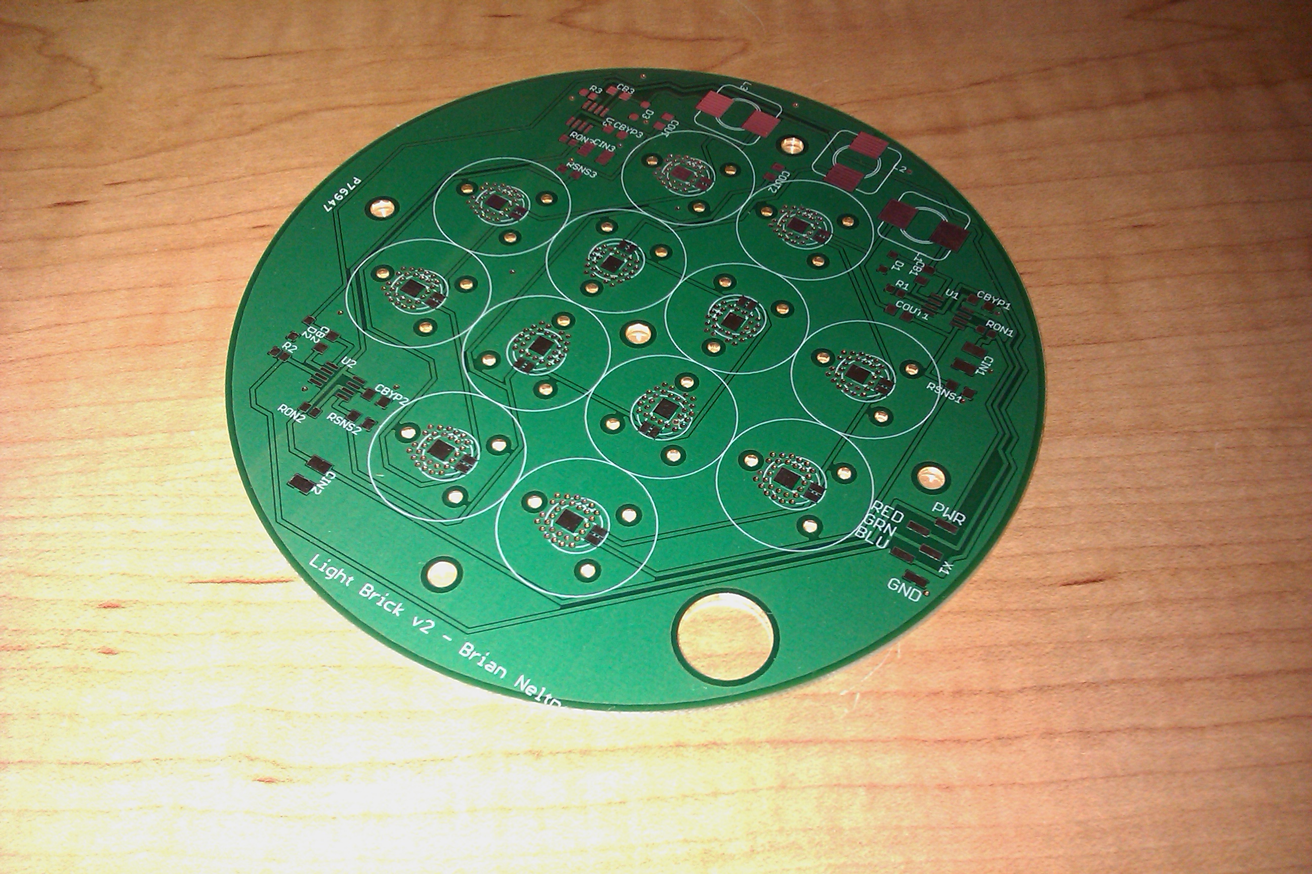
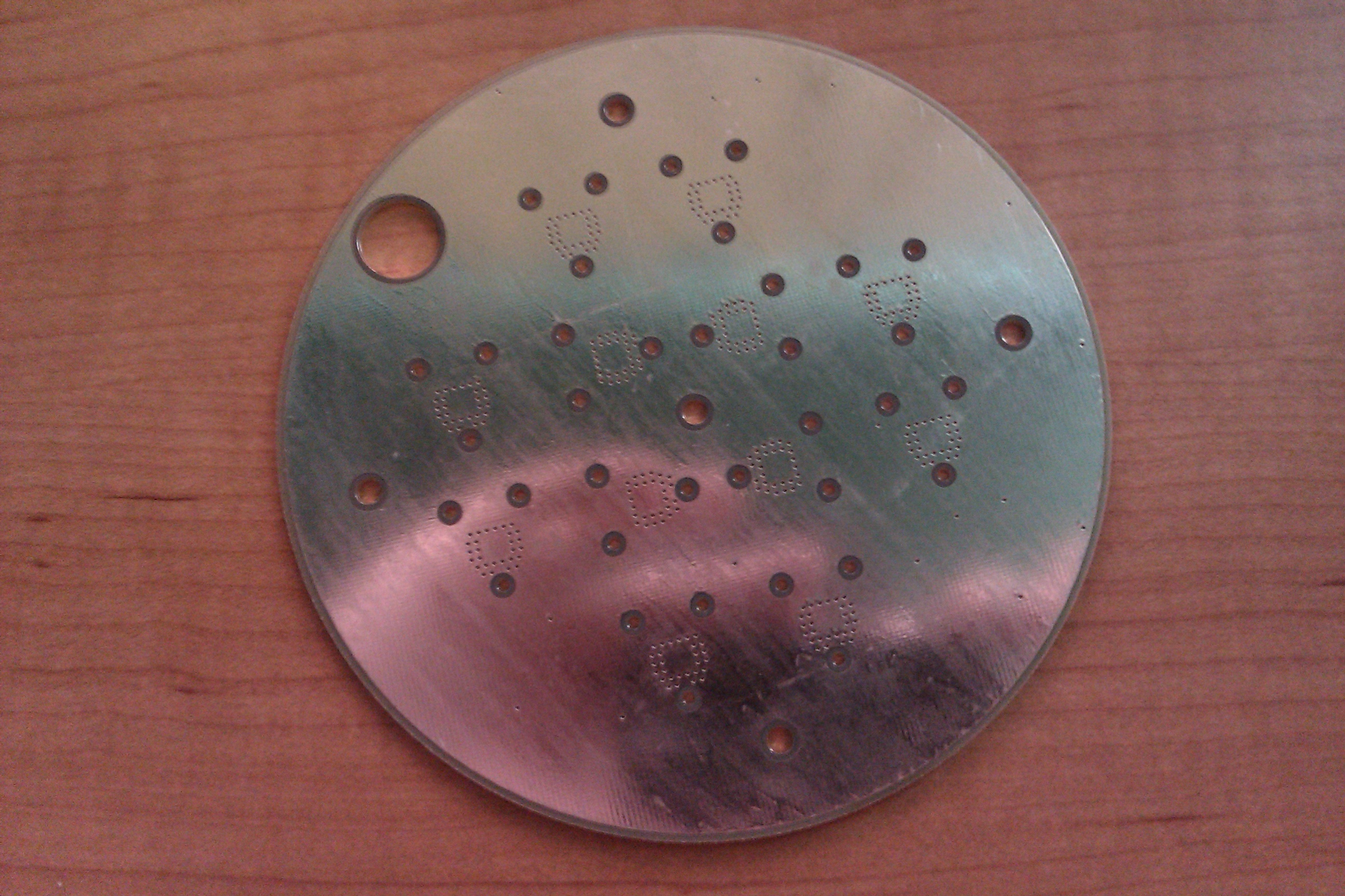
The advantage of laying out the board with all the traces in a single layer are significant. The biggest benefit is that because the Rebel LEDs are electrically isolated at their heat sink, I can make a single, continuous heat sink on the back of the board in order to very easily cool the LEDs. Secondarily, I don't have to worry about short circuiting traces through the case the board is bolted into. You can see the bottom of the board below, where every visible hole (via) is grounded and connected to the LED heat sinks.
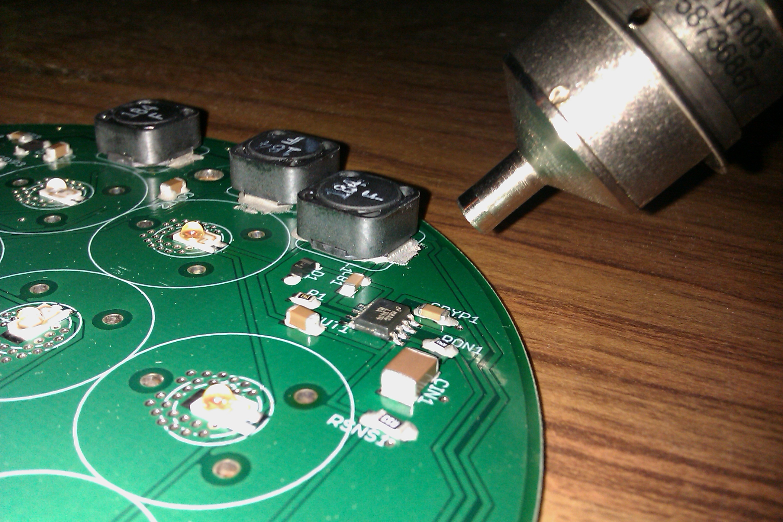
Next, I added a great deal of input protection to protect against some user error in connecting the device. Between a fuse, eight input protection resistors, three zener diodes on the digital lines, a large 5W zener diode on the power input line, and a full bridge rectifier, it should be possible for the user to plug the wires in backwards, connect line voltage to the device briefly, have a noisy signal line, or other usually nasty errors without completely destroying the board. Of course, there will be a somewhat difficult SMT fuse to desolder and replace to repair the board in the event of catastrophic failure, but that's a good sight better than replacing all of the tiny chips!
For assembly, I used my new Weller hot air rework station to make sure that the LEDs were soldered without any residual stresses that could make the joints come loose over thermal cycling. The way to do this is to first put down a small amount of solder paste on the thermal pad and the two pins, and then heat the entire thing up simultaneously using a two-output air nozzle. This also serves the purpose of "replacing" the LEDs into their correct seating on the board as surface tension from the melted solder pulls the part into position. It's actually a fascinating thing to watch as the LEDs "jump" into their correct, centered position (this is important for making them correctly placed for the optics!).
Next, I soldered all of the passive components, by putting down a dab of solder paste on each pad and placing all the components. In this case I used a 5CC syringe of unleaded solder paste from digikey.


Finally, it's time to use the single nozzle of the hot air station to heat up the passive components, reflow the solder, and pull the components into place! This step may have actually been easier to do using a standard soldering iron, but mine was out of order!

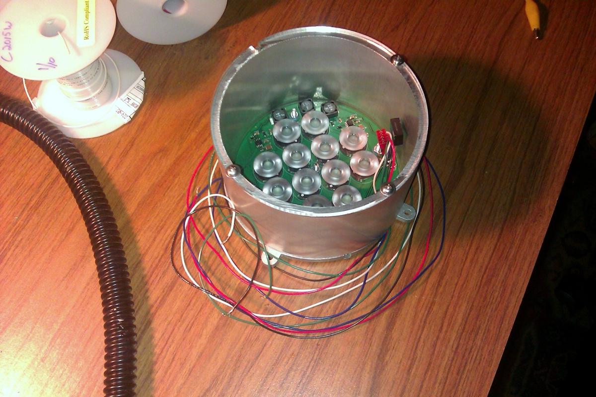
The last step in board assembly is then to attach the optics -- in this case OPC1 style optics from Dialight. They're great! There are three tabs to guide it into the correct position (which is good so long as your LEDs are centered properly from reflow soldering them), and they are adhesively backed so that they stay in place. They also look quite snazzy, in my opinion. A very attractive board!
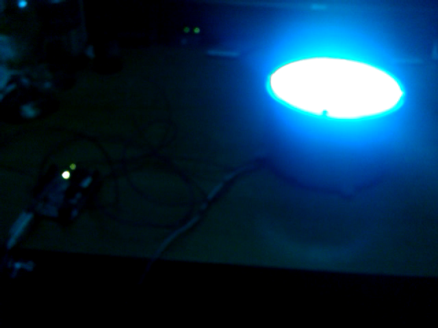
Now to power it on, I attach 20VDC or so across power and ground, and then touch the control pins with 5VDC (current limited, just in case on the digital lines!). Below you can see me manually touching the control pins for the red, green, and blue channels one at a time.
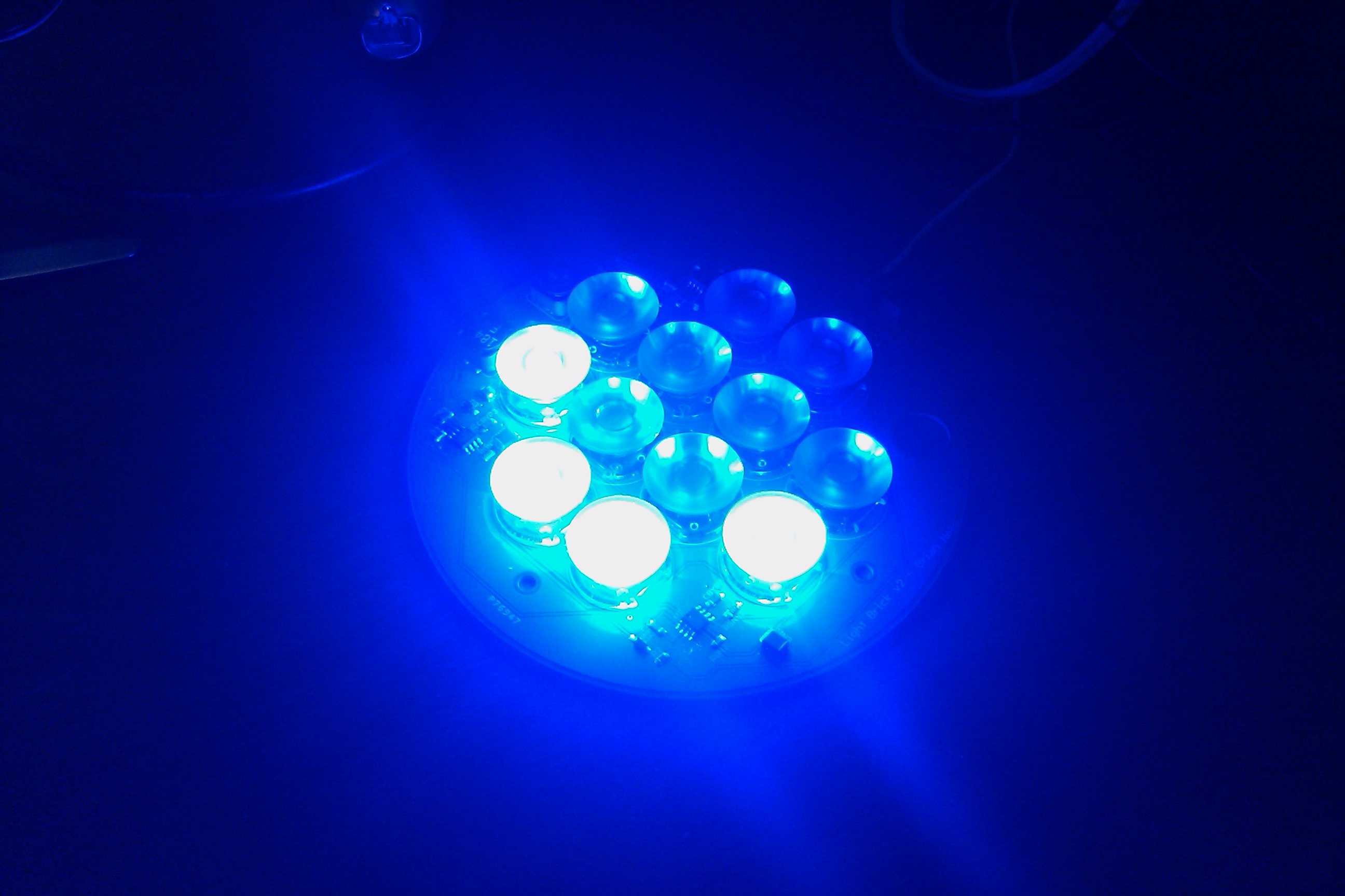
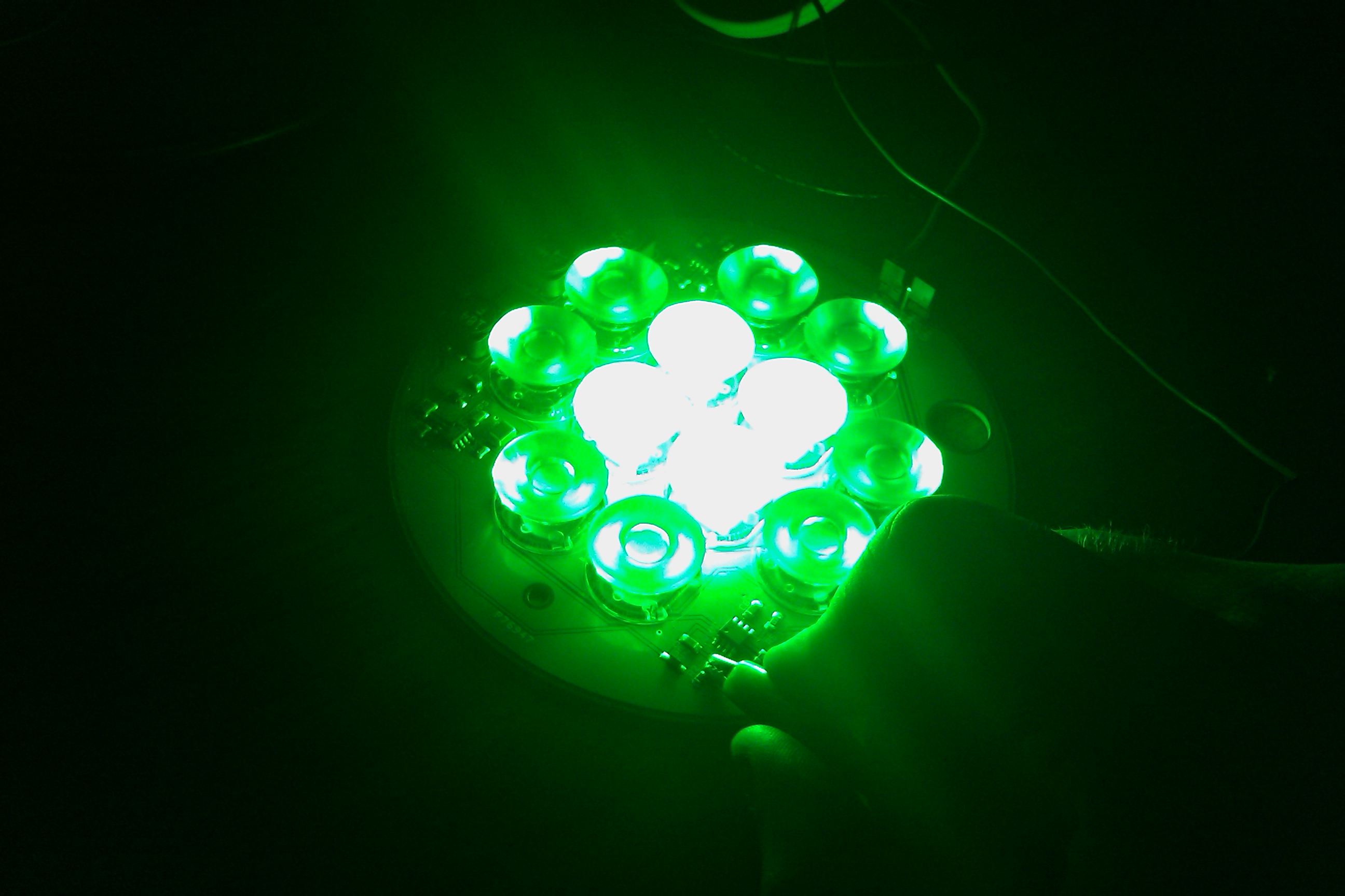
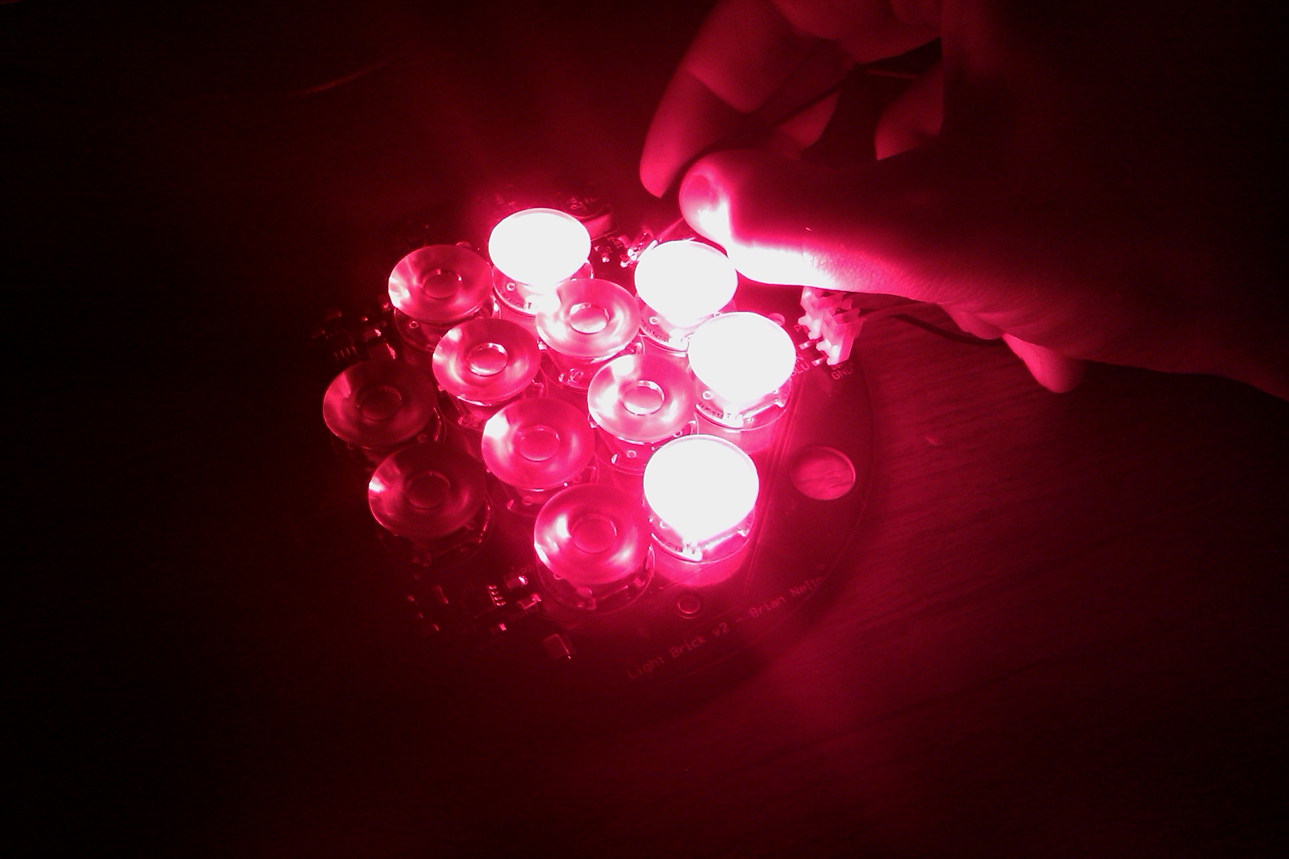
The final device puts out around 1000 lumens of light, assuming 80% optical efficiency (i.e. 20% of the light is lost to the optics and LED inefficiencies). These particular optics focus the beam down to a 7 degree cone, and even from this wide angle that the photos are taken from (around 45 degrees), it's pretty obvious that you wouldn't want to look straight into this one! I turned it on full white, and was able to basically replace the light output of the 60W incandescent overhead light in my room!
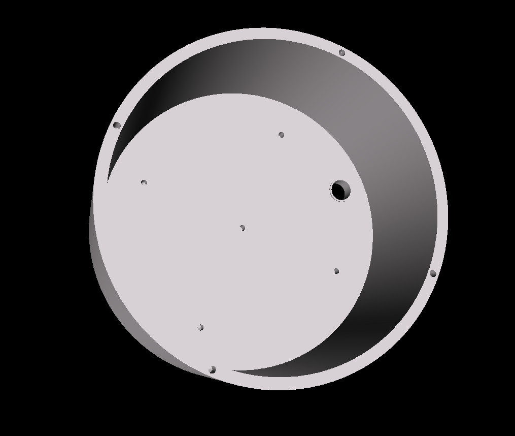
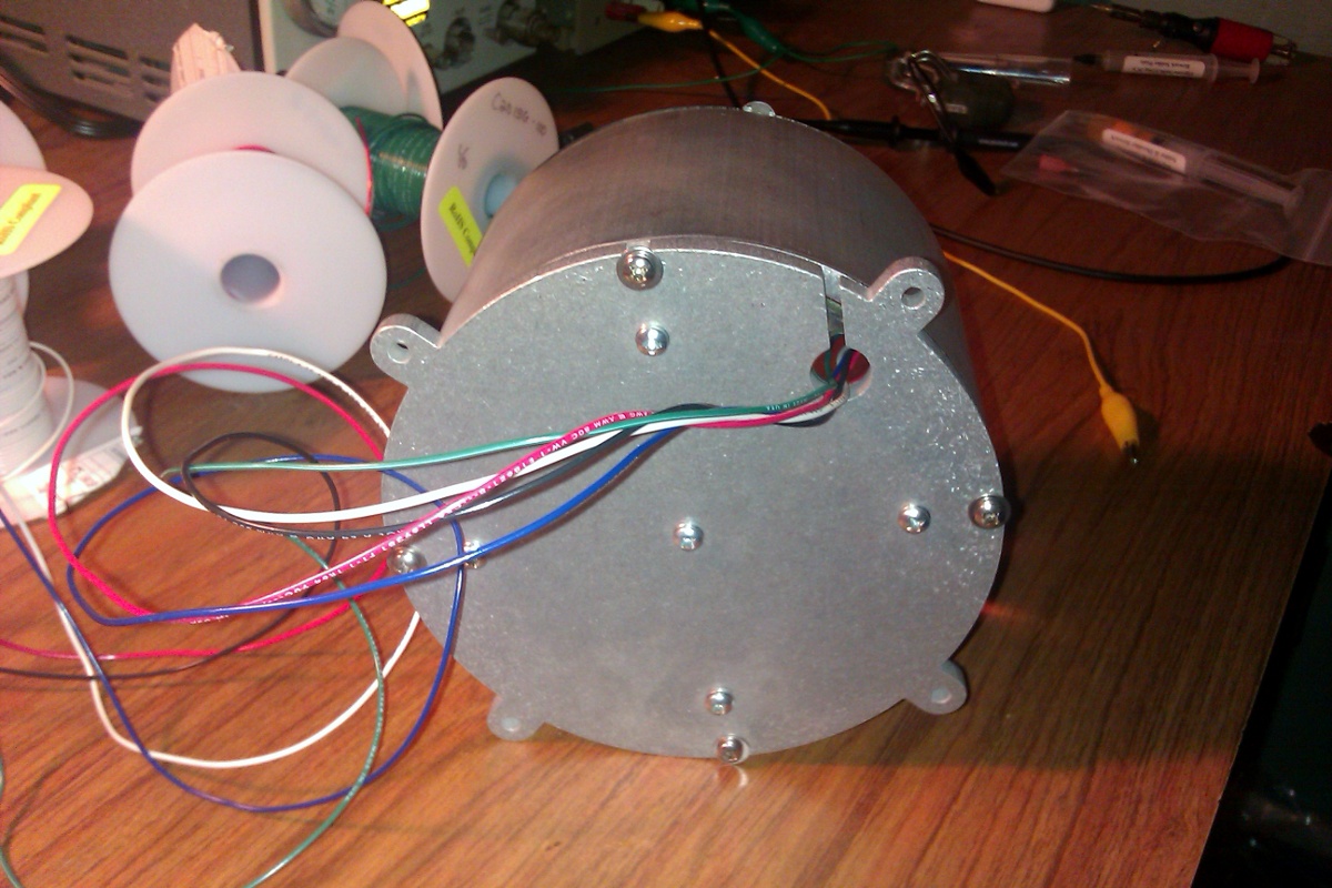
The cases are now finished, with the design is intended to be as inexpensive as possible while still being totally sweet. The design being done is a machined 1/4" aluminum plate for the back. There are holes in appropriate places for board mounting, and a .4" hole for a Moffatt hollow flex arm and then wires to pass through. The most up to date design has the wires entering through a flex arm immediately in the back of the case, but the new cases haven't yet been finished. The old version had the flex arm entering in through an off-center hole, which isn't as nicely symmetric. I will post photos of the new boards and cases when they arrive!
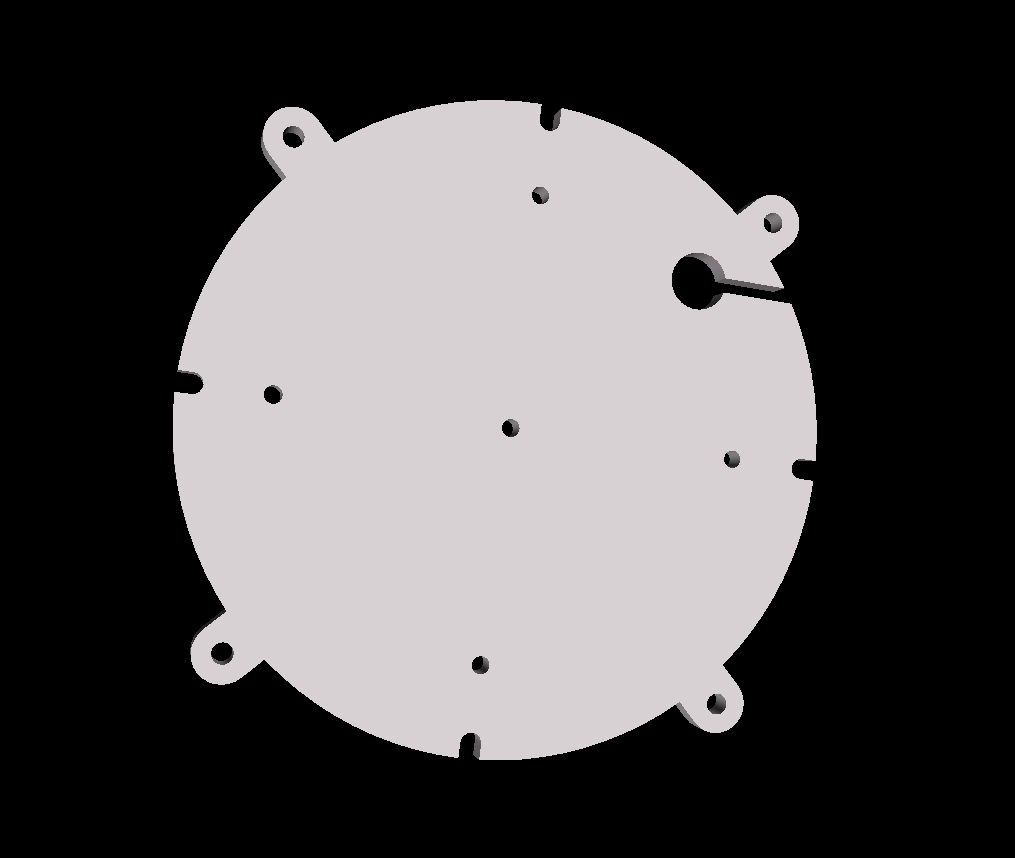
This plate also has four grooves in the sides, big enough for a #6-32 screw. These allow the back plate to be fixed directly onto a 5 inch aluminum pipe about three inches long with holes drilled into the edge, forming a round "can" light.
Finally, an acrylic lasercut cover is placed on the top, cut to perfectly fit the aluminum pipe and with four identical grooves to the base plate in it so that the acrylic piece can be attached to the end of the pipe as well. This protects the board fairly well from the environment, so hopefully it will survive burning man!
This is the final assembled result, and below you can find a movie of it working in a basic fading mode using code I wrote in about 20 minutes on an arduino. I made it on my android phone, and it is a ".3gp" file. I am not sure what that means, but my Ubuntu computer can play it. Hopefulyl yours can too!
Compared to the Ultraluminous Illuminator, this device is a lot simpler and cheaper to build. For a hobbyist, I think this device may be a lot better because it allows the builder to integrate it with whatever kind of system they are familiar with to output control signals of any kind they wish. Overall, including purchasing the boards, having the case parts custom machined, and including the components for the board, I managed to produce five systems that could be sold at around $335 a piece (without a distributor, that is).
Much more exciting is that if there is enough interest, once I'm building 100 of these lights, I can get the retail price down to only $300 per system (including the case, which is actually an integral part of the device because it is so powerful -- it needs the heat sinking area!). Although this is more expensive than other hobbyist lights, I'm proud to say that this one is a heck of a lot better than the other ones I've seen around. For example, the BlinkM MaxM is cute and even looks well designed, but puts out all of 5 lumens or so. It doesn't even need to be heat sunk, yet is advertised rather optimistically as "more than 1000 times as bright as a standard LED. They're so amazingly bright they kind of freak us out (and should absolutely not be looked at directly, under any circumstances!)." And for $25 a piece!
Now, granted, this little module is not really intended for serious lighting throw, but 5 lumens? Really? My light is going to be roughly two orders of magnitude brighter than this little module, and for only around $300/system! Now that excites me, and makes me proud to be an engineer, and a hobbyist LED light designer! With any luck, this system will make it easy for people to really design some crazy cool stuff.
That said, if you have any interest in helping fund this research project by buying a prototype, or expressing interest in getting one once the price comes down to a particular point, definately please send me a note so I know whether or not I'm wasting time thinking about scaling this up =) As is, five seems to be plenty for my personal use!
What I'd be really excited to see come of this is to be able to sell these systems on a hobbyist website like Sparkfun Electronics. They also sell the Arduino system, which has many sensor modules. Imagine how awesome it would be to have this connected up to, I don't know, a geiger counter and a microphone so you can have it flash red when it detects radiation, and then flash blue once it hears screams.
Okay, maybe that's a stupid idea. But that's sort of the point. I'm good at designing hardware, but I only have so many ideas on my own. I'd be thrilled to see people buy these, come up with awesome new uses for them by integrating them into their own projects, and then publishing the code so that we can build up our cumulative expertise. I'd love to be at the point where there are a dozen or even a hundred individual hobbyists who've done crazy cool stuff with this light (or others like it) and published it online to inspire the rest of us! So, in that spirit, please let me know if you are psyched about getting involved in bootstrapping a hobbyist group like that! I have lots of ideas, but I'm sure many of you have way cooler ones than me =)
Another alternative is to collaborate with a specific group to design complete light fixtures, and then sell those to end users. However, I'm not all that interested in getting deeply into business, so that will have to wait until I have some interested partners.
You can also check out the places where this system has been used in the Installations and Applications section. So far, it's been made to work with Arduino, the totally amazing Leaf Labs Maple Board, a higher processing power hobbyist board designed to be pin compatible with Arduino Shields, and the folks at Leaf Labs managed to make their Maple Board control the lights using an entirely wireless interface by using the async_labs WiShield. R.J. Ryan and Perry Hung wrote some amazing software that allows a user to take advantage of the aubio library, a sweet sound analysis suite usable in C, Python, and other languages for analyzing realtime or pre-recorded music and extracting relevant features from the sound such as the beats, transients, and other cool stuff!
