Touch Sensor Handle
Space Crisis; Who's driving this thing?
Handle Design
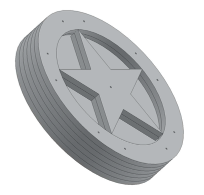
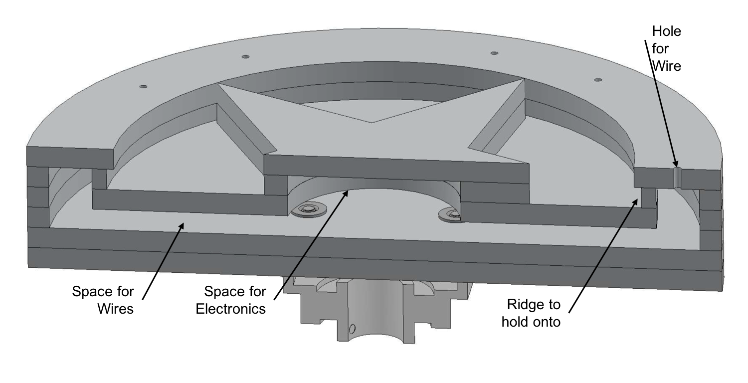
A touch sensor handle was made so that the players could have something to hold onto as they were directing their spaceship and navigating the stars! The handle has a laser mounted in the center of it that only turns on when all of the players are holding onto the touch sensors (green circles) of the handle. The handle also spins for added fun, and to allow the users to shift their body weight while still holding the sensors more easily.
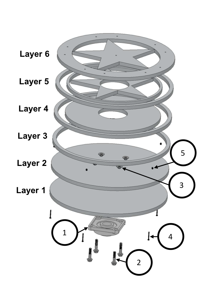
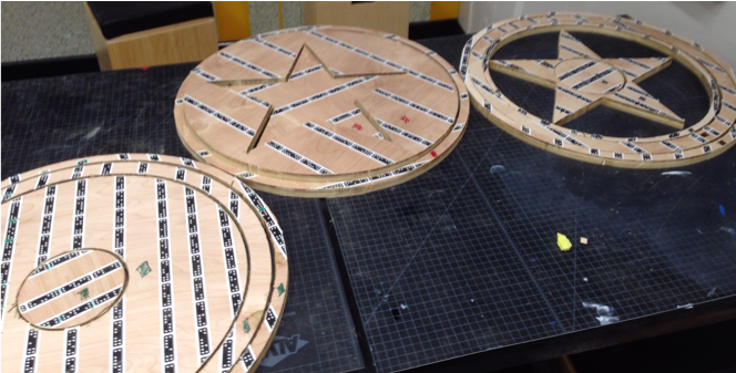
The handle is made up of 6 layers. The top piece is made up of 4 layers and the bottom is made up of 2 layers. This layering technique made it easy to cut the handle prototype out of 3/4 inch plywood using a CNC router. The final design of the handle should be machined out of a solid piece of aluminum for durability. The various components that make up each layer are shown below, and SolidWorks models for these components are available here.
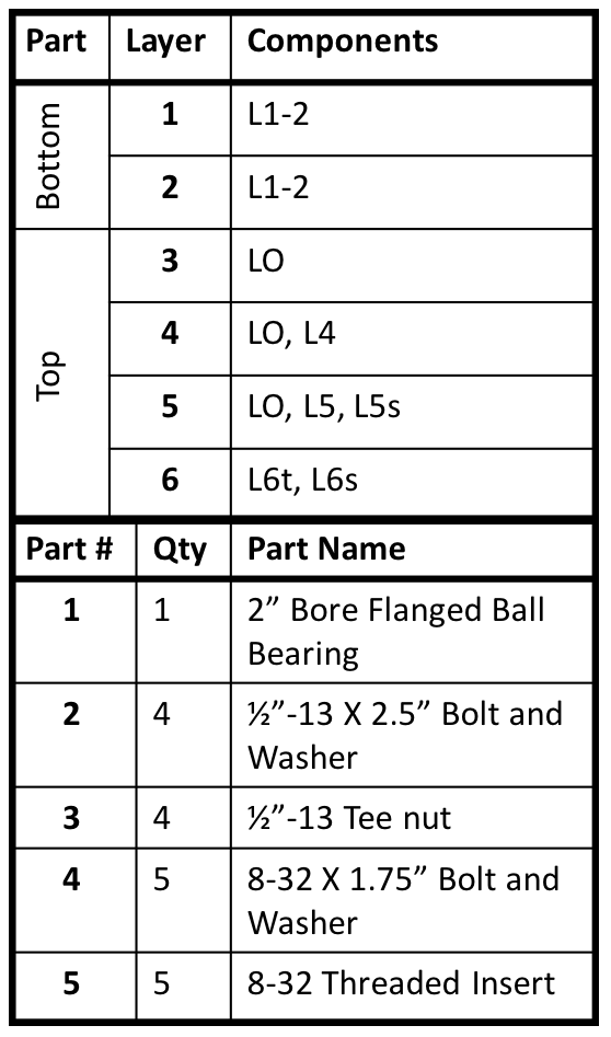
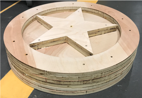
The design of the assembled components has important features when assembled together as shown in the image below. The top layers have hollow features to allow for electronics, wires, and the laser to be mounted inside the handle. A ridge was also designed to allow users to be able to hold onto the handle easily. Also, special care was taken so that the bearing was mounted to the outside of the handle’s base so that the handle could spin (for added fun). Mounting the bearing on the outside of the handle allowed the handle to spin without interfering the electronics and wires that were mounted on the inside of the handle. Also, all of the wires and electronics can be mounted to the inside of the top piece of the handle, so that the electronics can be easily inspected by removing the top and flipping it over.
Building the Handle
The various components were cut out of plywood using a hand-held CNC machine called the Shaper Origin. Then the layers were assembled together with wood screws and wood glue to make the top and bottom pieces of the handle. Hardware was installed to connect the top and bottom together, and to mount the flanged bearing onto the handle. Threaded inserts were drilled into the top piece of the handle and holes were drilled into the bottom so that five 8-32 bolts could be used to join the top and bottom pieces of the handle. The bearing was mounted to the bottom of the handle with four 1/2 inch tee nuts and bolts.
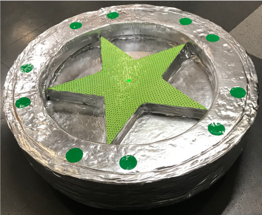
Then 1 inch upholstery foam was glued, using contact cement, onto the top of the touch sensor ring and around the outside circumference of the handle for safety. To make the handle look more futuristic, to fit the space theme, silver and green 2-way stretch fabric was glued to the handle, and green vinyl stickers were used for the touch sensors. An image of the final prototype is shown below.
Electronics
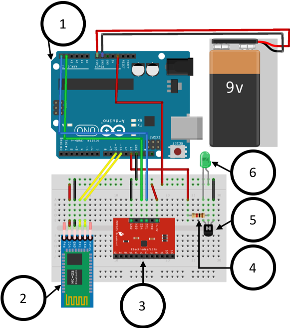
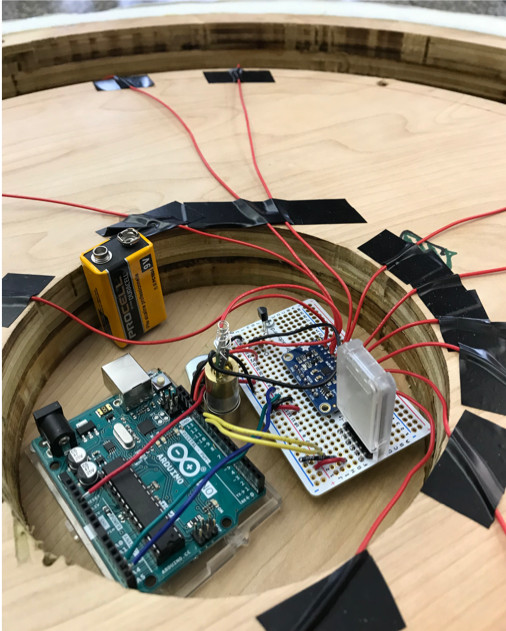
Electronics were placed in the handle so that the laser would not turn on until all of the players were holding onto the handle, which insures proper and safe gameplay. This was achieved by using capacitive touch sensors and a green laser module (green was used as it is easier to see). Also, since we did not want wires hanging from the handle, batteries were used to power the electronics and a Bluetooth module was used to monitor the code output as well as change some parameters of the code. The wiring and modules used are shown in the image below.
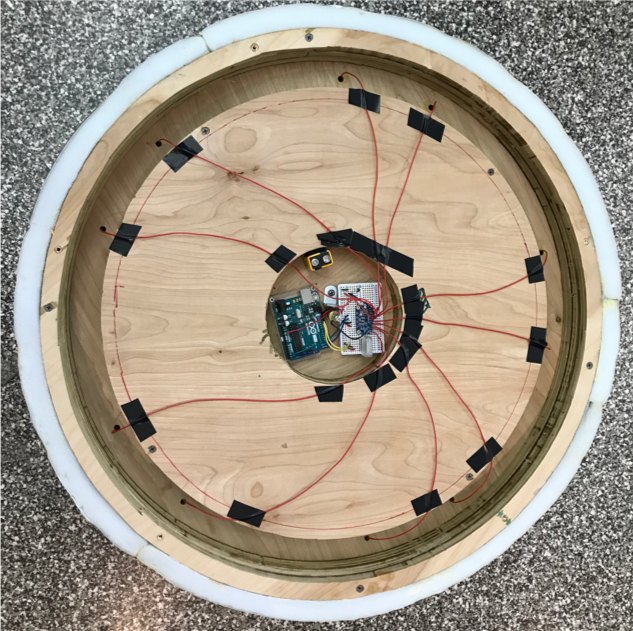
The electronics were mounted in the handle using screws, brackets, Velcro, and electrical tape. The hollowed out sections of the top of the handle allowed the electronics to be easily mounted and the wires to be easily threaded to the various touch sensor locations on the outside of the handle. Once threaded through the wires were taped to the top of the handle with copper tape and then a green circle vinyl sticker was placed over the copper tape. The green circles marked where people where supposed to hold onto the handle. But, as people pressed down hard on the sensors they indented and would sometimes not make as good of contact with peoples hands, which led to sensor misreading. A redesign of the touch sensors would be needed in a final design to make them more durable and reliable under large pressures.
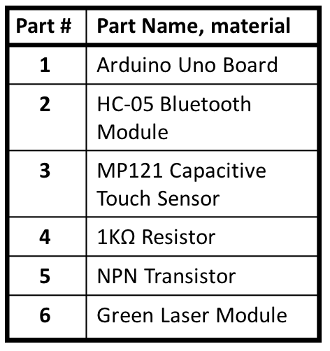
To electrically prototype the touch sensors Arduino Uno and Adafruit MPR121 Capacitive touch sensors were used. Ten of the touch sensors were connected to wires and capacitive tape and then hooked up to the Arduino board and a green LED. Code was written in which the number of people entering the room was input, then this number was multiplied by two to define the number of sensors that needed to be touched for the LED to light up. An example of the code and sensors working is shown below. In the video an input of 2 people was given and the LED will only light up when 4 sensors are touched. If too many or too few sensors are touched the LED turns off. The Arduino code is available for download here.
Improvements
- Have the bearing no longer be self-aligning. This would make the bearing still able to spin, but not able to be pulled down and up, which would be better for durability and safety.
- There was a problem with the touch sensors becoming indented. To avoid this a more durable button-like touch sensor should be designed.
- The entire design should be built to last, so a more durable and easily machined material, like aluminum, should be used for the handle instead of plywood.