
Ball Collection Grid
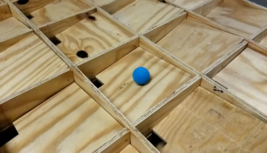
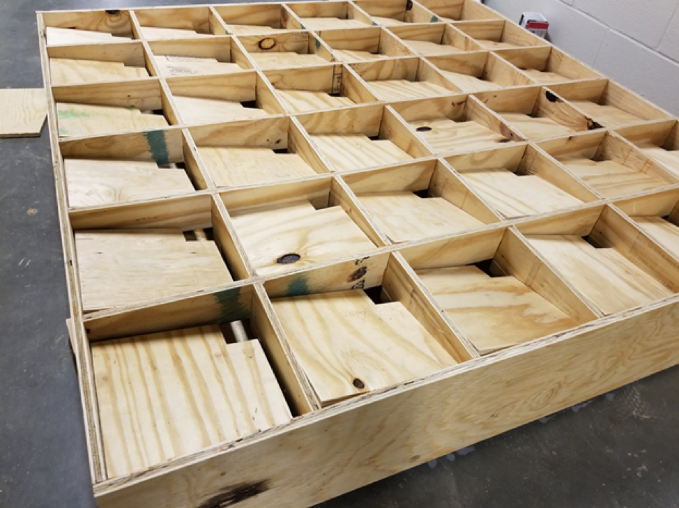
To begin construction on the ball detection grid, we first finalized the design parameters and characteristics. We settled on wood for rigidity and durability to withstand the impact of the balls. Our designed incorporated 36 individual grid cells in a 6x6 square at a half scale model, with the actual dimensions being 9' x 9' x 18". Each cell housed a square panel, angled toward one corner to direct the balls using gravity. Once the balls pass through this hole, they land on another sloped square filling the entire area of the grid, also sloped to one corner. This ensures every ball that lands on the grid is sent to the same location every time, and allows for effective return of the balls to the players.
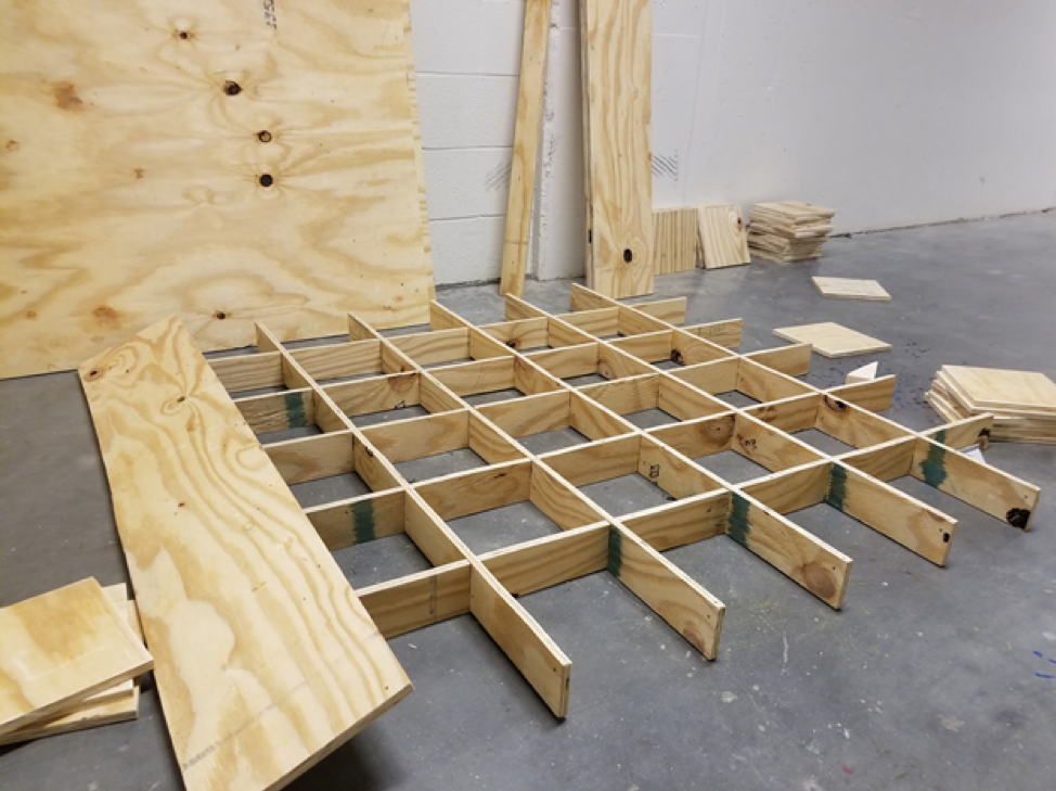
To create the grid, ten thin slats were made with rectangular notches dimensioned by the thickness of the wood and one half the slat height removed at five equidistant indices. This allowed the slats to lock into each other vertically and horizontally to partition a 6x6 grid.
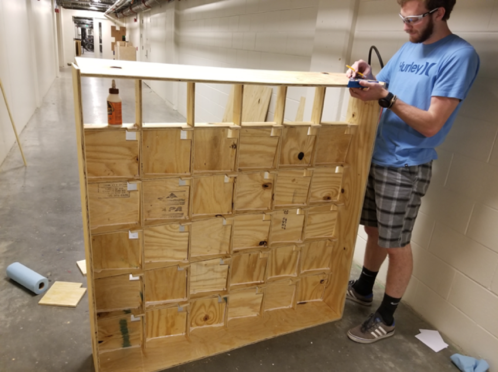
The four outer walls of the entire box wore added, enclosing the grid. The slanted panels in each square were pressed in and glued to the structure. This proved to be difficult as the slanted panels required relatively precise dimensions to comfortably fit in the established grid. The thickness of the plywood affected the ability of the panels to stay at an angle yet also helped wedge some panels in more tightly.
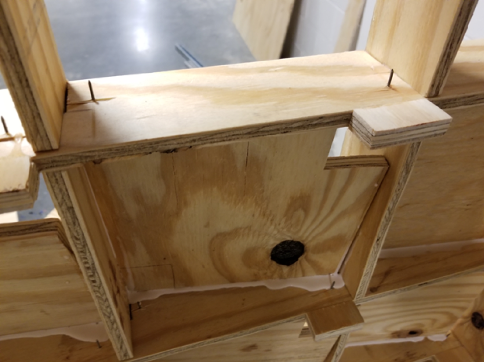
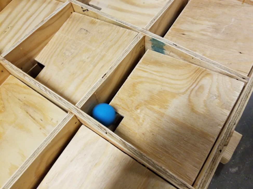
Looking closer at each of the slanted grid spaces, we can see how they are assembled, and where there is room for future development. Each of the grid spaces are geometrically fit to be snug at a slight sloping angle, and a cutout just large enough for the projectiles to pass through was cut as well. For assembly purposes, placeholder nails were put in to assist in alignment, with eventual construction completed with a press fit and reinforcing wood glue. The small rectangular piece in the upper right of the figure is a space left for the placement of an optical sensor to detect which square the balls land in. Each sensor is to be placed such that it has a clear line of sight to the area directly below the hole in the corresponding lid.
Another approach for sensors that was explored was mechanical or tactile switches. With repetitive use, these are not as ideal as the optical sensors, but can be installed somewhat more simplistically by placing them directly under the corresponding hole. Other issues arose in the construction of the entire apparatus as well, namely some geometric considerations and material selection.
Instead of slanting each of the individual squares and the lower surface of the grid, everything could have been made perpendicular, and then the entire box could have been slanted instead. This doesn't change the performance of the game, but was a simple oversight made by us primarily due to low amounts of sleep.
The other large issue at play here is the material selection of both the box, and the ball. Making it all out of wood gave us a lot of flexibility in construction, especially considering the tools we had at our disposal, but the elasticity of the wood proved to make the gameplay quite difficult. This coupled with a ball that didn't have the lowest coefficient of restitution meant that the ball would be bouncing all over the board, and the game became much more a question of luck rather than skill.
Another design consideration that should be taken into account is if slanting the individual squares is the most effective way to funnel the balls back to the players. Although this does work, ideally the side walls would be taller, and the bottom would be flat or even conically in an effort to keep the balls in the original location to which they were thrown.