Circuit
Final Design and Prototype
For the final prototype, a matrix circuit is used to minimize the number of IO wires required. The different circuits explored is outlined in the concept refinement stage.
Sensing Matrix Circuit
The matrix circuit can be observed in the circuit diagram below. A1, A2, ... represents the rows while B1, B2, ... represents the columns. A single row represents each shelf while the columns represents all the switches on each shelf.

The matrix circuit works be sequentially scanning each switch at the (A,B) coordinates. For example, to check the state of switch(A1,B2), A1 is thrown to "high" while B2 attempts to read the voltage. Due to the open switch at position (A1,B2), B2 would read a "low" state. This repeats for each column followed by each row.
Although it is not represented in the figure above, one jar involves 4 of the switches in 1 row. Hence, there are 5 rows and 8*4 columns. This would require 37 main wires and IO pins, greatly simplifying the circuitry. Furthermore with a 16MHz microcontroller, we can easily scan the whole matrix thousands of times per second, ensuring that there are no lag in the responses. The diodes in the circuit prevent a phenomenon called ghosting which is explained further in the concept refinement stage.
Final Prototype
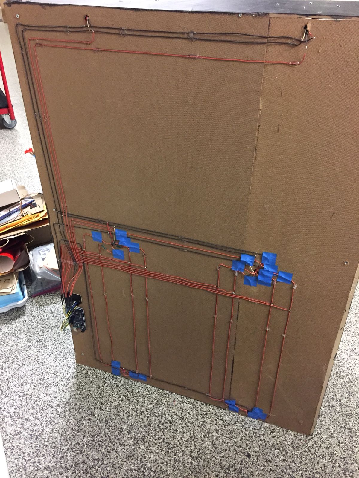
Even though the wiring looks really complicated in the figure above, the number of wires has already been reduced greatly. There is a total of 10 main IO wires and 4 LEDs wires instead of the usual 20 main IO wires. The wires were meticulously laid out to show the layout of the matrix circuit.