Constellation Lights
by Emily Hanhauser
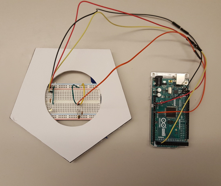

Through sketchmodeling of this subsystem, I wanted to explore:
- implementation of a photocell circuit on a breadboard (especially since this is really my first foray into electronics!)
- the distance and pitch at which the photodetector can sense the laser beam (as well as the response time)
- a potential way to string multiple circuits together to create a constellation
Basic photoresistor circuit
A photocell (aka photoresistor) is a light dependent resistor (LDR). I used the most commonly available size of photoresistor, a 5mm x 4mm square oval. To monitor the decrease in the resistance due to incident light, a voltage divider was constructed using a pull-down resistor and LDR. The output voltage was monitored via the serial monitor in Arduino software. Through measurements in ambient light settings, it was found that a 1 kilo ohm pull-down resistor worked well to distinguish when the laser had hit the LDR; which allowed me to set a threshold for when the laser hits the LDR.

To show the photoresistor has been hit, I constructed a program that changes an LED from blinking to on when the voltage output from the voltage divider increases. This program then resets, allowing me to test the set up repeatedly. This is demonstrated in the videos below. The response time is very fast; the laser only needs to remain on the sensor for about a second to trigger a hit. An available red laser was used in all of this testing; however, based on feedback, we will switch to a green laser for better visualization in the real game.
A potential drawback of using a photoresistor is that the threshold for a target being hit would have to be set for each different lighting. This may be able to be overcome by using a program that tracks hits based on a difference in voltage.
Details of laser detector
The photocells will be incorporated into stars that hang from a mesh network across the top of the room, 10'3" above the floor. To test the maximum distance at which the laser can trigger the LDR (and thus the maximum area on the mesh in which the star sensors can be distributed), I attached a mock star to a breadboard and secured the breadboard and Arduino to a pole previously used in sketch-modeling. This pole is 7 feet tall.
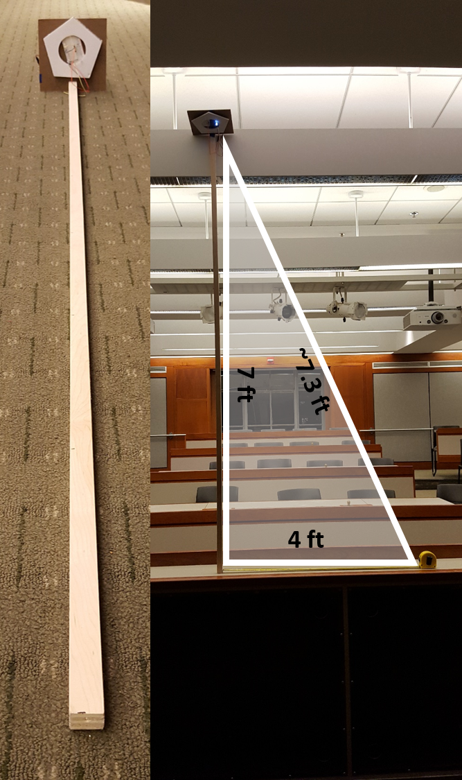
The laser could reliably trigger the sensor at a distance of a little over 7 feet away; this is very encouraging, given that the sensor area is quite small and we were concerned about potentially needing the shots to be very accurate. In the current platform design, the laser is 5.6 feet from the ceiling. With a maximum laser to star distance of 7ft, this corresponds to a sensor distribution circular area of 25 square feet.
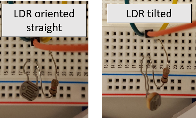
Of all areas, shots from the side of the sensor took the longest to orient and ultimately trigger a hit signal. A potential fix to this is to orient the outer star sensors towards the laser; this was performed and found to help in making these shots easier. Additionally, it was found that the LED must be positioned below the sensor surface to minimize effects from the LED light.
Potential software for constellation of star sensors
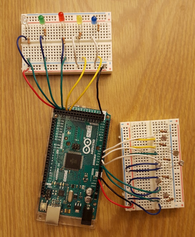
To test a program for five sensors that must be hit sequentially, I constructed a circuit on two breadboards, one holding 5 LDRs and the other holding 5 corresponding LEDs, with similar connections to the breadboard shown above. A blinking light is the signal that a star needs to be hit. Each time a LDR is hit, the corresponding LED turns from blinking to on. The LED corresponding to the next target in the sequence starts then starts blinking. This circuit and program worked quite well. While this prototype has the LDRs and the LEDs separated for simplicity, the actual star sensors will have a LDR and LED on the same board.
Concept refinement and rendering
From sketch modeling, the following key design attributes were identified:- The star sensors should be able to be tilted or repositioned so that the LDR can be oriented towards the laser for easier target hitting. This also allows for flexibility in constellation design.
- The LED must lie below the LDR in order to minimize interference, but the LED should be near enough to the LDR so that aiming towards the light triggers the sensor
- It's possible that one white LED is bright enough to give the intended glowing effect to one star. Additionally, the star should be translucent or frosted to make the light more diffuse
- Each star will have a PCB/protoboard that had an LDR and LED(s) (and potentially other light effects that we are exploring). This needs to sit securely in the star, but also be accessible for wiring to the Arduino microcontroller.
- Based on guidelines from 5Wits, the mesh structure used to hang the stars must not interfere with the powering or sprinkler system, but be robust enough to hold multiple star sensors and decoy stars.
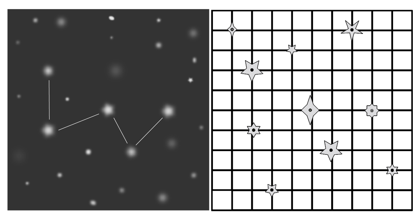
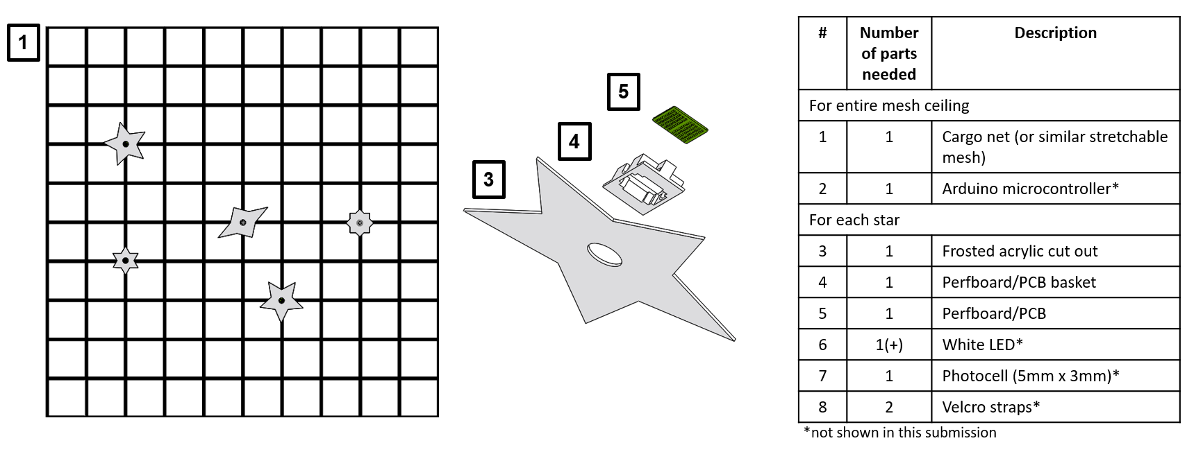
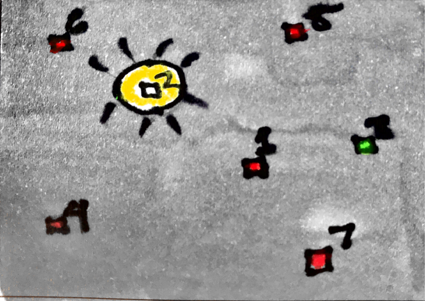
As a starting point, the constellation of Cassiopeia is selected for this room, a group of 5 stars. A rendering in Illustrator shows the ideal version of what the constellation ceiling mesh would look like. A corresponding CAD modeling of a 9'x9' square ceiling was constructed to show how the stars might be laid out on a mesh in attempt to model a night sky. The stars in the room are comically large, in an effort to be more obvious and attractive to players. A strechable mesh, such as cargo netting, is an ideal network to be used for the mesh support structure, since it is easily deployable, is porous, can be relatively easily mounted to the wall panels via hooks and provides enough hanging locations for a realistic looking starry night.
While creating an entire starry night would be the ultimate goal for this room, in our final prototype, we will focus just on the 5 star sensors needed to make the chosen constellation, as shown in the simplified CAD model.
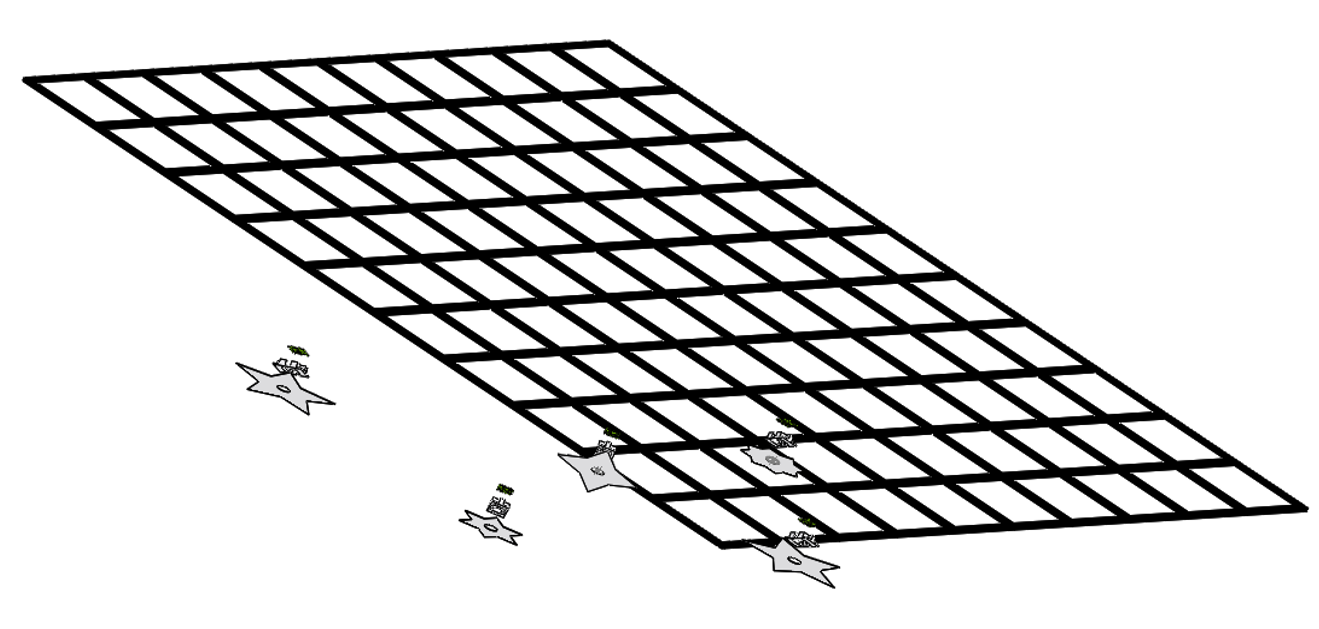
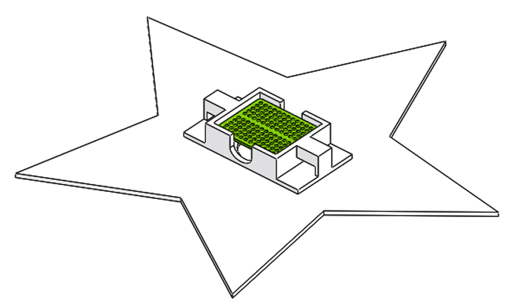
The star sensors are of various shapes, but all are made of 1/16th inch frosted acrylic. The hole in the middle of the star provides access to the LDR, which is connected to the protoboard sitting in a basket mounted (via glue or small screws) to the back of the star. The basket, which will be 3D printed for prototyping, fits a 1/4 size protoboard. It is constructed such that LEDs on the protoboard can fit between the basket and the back of the star, so that it does not interfere with the voltage measurement from the LDR. Additionally, cutouts on the basket allow for wires to emerge from the protoboard to connect to the Arduino. The slot in which the protoboard fits is taller than the depth of the board, thereby securing the circuit to the star. Further prototyping will determine if this is enough to secure the board to the star with tilting; if not, we will encorporate screw holes to better secure the protoboard.
Finally, on each side of the basket, there are two slot holes for hanging the star sensors from the mesh network via velcro straps or zipties. In this way, the pitch of the star is controllable, as well as the entire star structure being repositionable for creating different constellations.
