|
|
|
|
|
|
|
|
|
| Home | Program | People | FAQ | Get Involved | Photos | Sponsors | Links |
Here we have some current models of our SoccerBots. First:

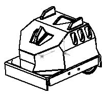
This is what the SoccerBot looks like when it is ready to drive. The part on the top with the fins is the Hat, which covers up the control box and all the wires.
On the lower right hand side, you can see the flipper paddle, which runs the length of the bot. A solenoid assembly fires the flipper, and there is one on each side. Behind the flipper, the bottom edge of the wheel can be seen.
The lower left side shows how the baseplate is bent to protect the delicate bits of the bot when the driver tries to drive the SoccerBot into a field of spikes. The bend is also handy for hitting the ball after the bot has achieved ramming speed.
Now:

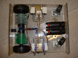
On the left, you see the motors in their mounts. The mounts are green. The motors come from cordless screwdrivers, and have wheels pressed onto the shafts. The blue stuff in between the motors is electrical tape preventing the motors from shorting out.
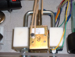
In the middle of the bot are the two flipper assemblies. Here is a close-up:

The shiny brass thing in the middle is the solenoid. It is a big solenoid. Next to it are blocks that supporting a u-bolt connected to the solenoid plunger and the flipper paddle. The rubber bands reset the solenoid after it fires.
Back to the bot, on the right you have two wheels on casters. In between is the battery pack, which is simply the rest of the cordless screwdrivers.
In and around, you see wires, which connect to the control box or tether, which drives the bot. The hat goes on top and is attached by velcro for quick and easy removal. For the contest, the different bots on each side wear official contest hats.
Some of these images created using Solidworks(TM) modelling software.
|
|
Contact us at dme-web@mit.edu. |