|
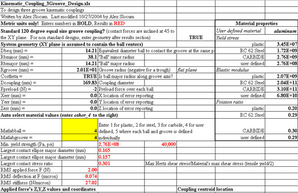
Intro:
Kinematic couplings serve as a reliable and affordable means to obtain both precision and accuracy in mating fixtures. Although the geometry for each coupling varies on the application or process, the backbone of the kinematic coupling remains the same: exact constraint. In order to obtain an exact constaint design there must be one contact for each degree of freedom of the system.
Theory:
The underlying principle behind kinematic couplings is hertz contact. The original theory was developed to solve a railroad industry problem; however, since then the number of applications has spread into many industries.
Some key concepts to keep in mind for hertz contact is: elastic deformation, exact constraint,
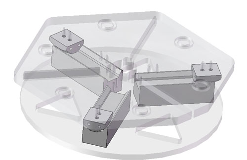
Design:
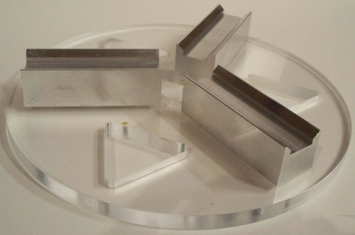
The design of the kinematic coupling was created with the potential to expand into different geometries. There are two circular geometries for the system: Radial contact at 2 1/3" and 6 1/3" OD. There are also slider pockets 120 degrees a part from each other and 60 degrees from the static references that allow the kinematic coupling to slide between a diameter of 2 1/2 " to 6 "; thus allowing for an adjustable kinematic system. Currently, the preload of the system is only its own weight which is about 5 Newtons.
Full Kinematic Coupling Assembly Model
Download Step File
E-Drawing
Simple Kinematic Coupling
Bottom Plate of Kinematic Coupling
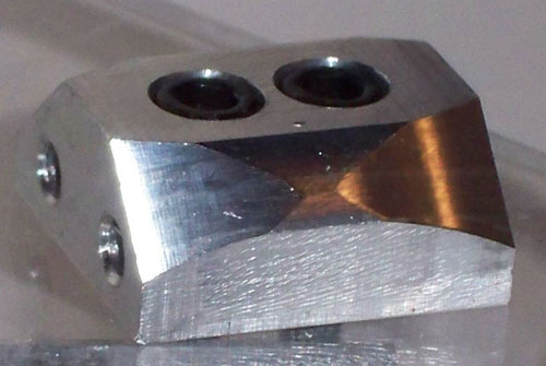
Coupling Head with Two Radii of Curvature
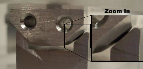
Zoom in view of the contact point.
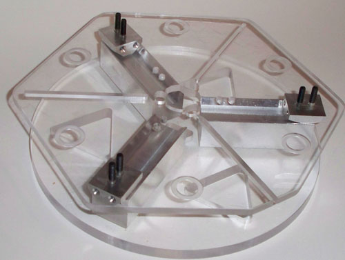
Manufacture:
The kinematic coupling shown above was produced using a Bridgeport CNC mill. The whole assembly has a total of eight components. The female coupling (3" rails) attached to the bottom plate were created from a solid piece of 1"x1"x10" aluminum bar then cut size. Dowell pins (1/8") align the rails, while 8-32 cap screws secure rails to the bottom plate. The three male coupling were also maufactured in the CNC Mill; however, two different setups were required to generate the desired geomtry of the system. Each male coupling had to be manufactured independently. Two 8-32 cap screws secure each male couplings to the top plate. Both the top and bottom plate were made using the CNC mill. Although both of the plates are made from clear plastic (unidentified), the thickness plates differ. The respective thicknesses for the top and bottom plate are 3/8" and 1/2".
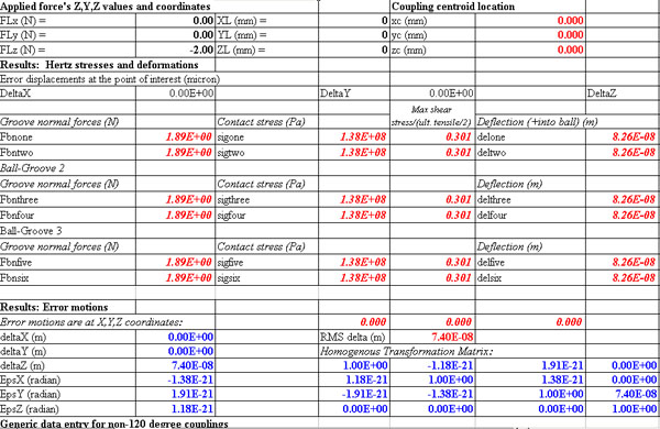
Measurement Results:
Measurement Results
| Run |
pt 1 |
pt 2 |
pt 3 |
pt 4 |
pt 5 |
pt 6 |
| 1 |
0.0000 |
-0.0150 |
-0.0190 |
-0.0175 |
-0.0140 |
-0.0015 |
| 2 |
0.0000 |
-0.0140 |
|
-0.0180 |
-0.0140 |
-0.0015 |
| 3 |
0.0000 |
-0.0145 |
|
|
-0.0140 |
-0.0015 |
| 4 |
0.0000 |
-0.0145 |
-0.0185 |
|
-0.0140 |
-0.0015 |
| 5 |
0.0000 |
-0.0140 |
|
|
-0.0145 |
-0.0015 |
| 6 |
0.0000 |
-0.0145 |
|
-0.0170 |
-0.0135 |
-0.0015 |
| 7 |
0.0000 |
-0.0145 |
|
|
-0.0140 |
-0.0015 |
The measurements were taken using a dial indicator on a CNC mill. The dial indicator was loaded to 15 mil and the z reading was taken from the digital readout of the bridgeport.
Discussion / Conclusion:
Although the results do not match those calculated from the analysis, the concepts that led to the design of this kinematic coupling remain true. Some of the error measured originates from the measuring technique which relies on visally aligning the dial indicator to the center of the measuring spots.
|