|
Key Individuals
Jim Elliot --- Project Supervisor
Amanda Gulbis--- Principle Investigator
Folkers Rojas --- Chief Engineer/Designer/Machinist
Vern Stahlberger--- Preliminary Design
John Rayner--- Optics Specialist
Objective
The objective of this project is to provide an interface for the Portable Occultation Eclipse and Transit System (POETS) camera to mount to the IRTF telescope in Hawaii.
Design Parameters
- Light Tight
- Ability to adjust focal length
- House 3 Optical Lenses
- House a 8 lense filter wheel
- Connect to POETS
- Alignment (Eccentricity = 0.002" , Location .003")
- Time to Design, Manufacture and Test at MIT: Four Months
Design & Manufacture
The design is subdivided into four four modules: 1) Casing, 2) Z-Extension, 3) Interior Accessories, and 4) optics holders.
Casing (Download PDF Binder of Drawings)
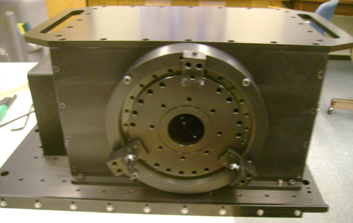
The casing section consist of eight individual parts to make the case. The preliminary design was done by Vern and John working from Hawaii. The base platform was produced by Hawaii, which constrained the design of the rest of the case.
The four walls of the casing are held togetherr via sixteen 1/2" x 1/4-20 Stainless Steel cap screws. The access cover joins to the four walls via twenty four 3/8" x 1/4-20 Stainless Steel Cap screws. Only the bottom portion and top portion of the case connect to the base. The alignment is secured using dowell pins.
 Casing Front Side towards Z-Extension Casing Front Side towards Z-Extension
 Casing Back Side Casing Back Side
Z-Extension (Download PDF Binder of Drawings)
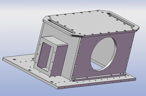
Due to an error in the preliminary optical design and the manufacturing of the base plate prior to checking optical design, it was necessary to add an extension to the case in order to compensate for new optical path and still use the manufactured base plate. An advantage to the Z-Extension is that it allows for moving poets along the optical path.
The exterior disk of the Z extension joins to the bottom lid of the disk via four 1.5"x 1/4-20 stainless steel cap screws. The alignment is done via an oring lip that fits into the hole on the bottom lid.
The whole Z-Extension Assembly is composed of five parts. For a detailed description on each part and how they assemble download PDF binder of drawings.
 Z-Extension exterior view Z-Extension exterior view
 Z-Extension Interior view Z-Extension Interior view
Interior Accessories (Download PDF Binder of Drawings)
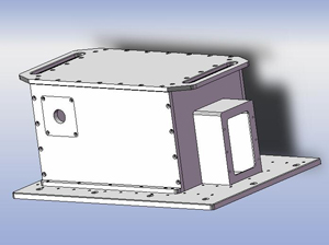
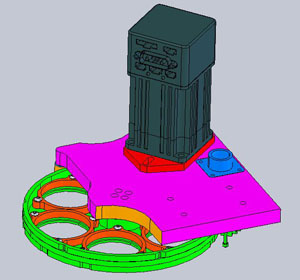
The interior accessories category is composed of any part that is inside the casing but does not hold optics. There is a total of four items that fall into this category. This part were designed to work and maintain a low cost budget; therefore, many aestheic features were not included. The parts were made with functionality and rapid production in mind. The figure below show the interior accessories isolated and incorporated inside the case. The incorporated view also shows the filter wheel stand for holding the filter wheel.
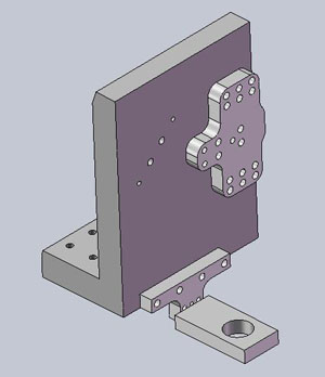 Isolated View of Interior Accessories Isolated View of Interior Accessories
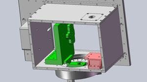 Incorporated View of Interior Accessories Incorporated View of Interior Accessories
Optic Holders (Download PDF Binder of Drawings)
There is a total of four optics and three optic holders.
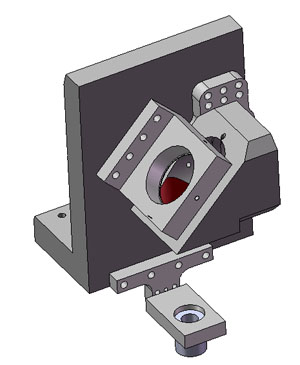 Optic Holders Optic Holders
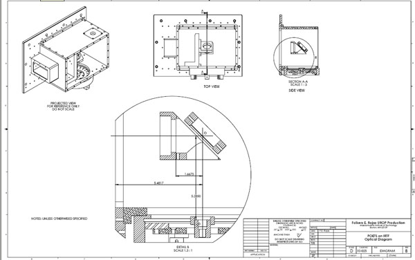
Optical Diagram (Download PDF Drawings)
The optical diagram was imported from a ray tracing done by John Rayner, part of the Hawaii group. The diagram was created in Solidworks. This is the only diagram that is measured in millimeters, since all of the optical design was done in metric units.
Optic Diagram
Other Components
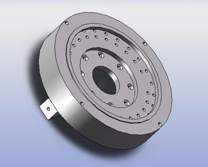
Filter Wheel
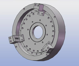
The filter wheel used for this project is a purchased item. A 3D STEP file was provided by Hawaii of the filter wheel. All of the design was done assuming that the 3D parts were accurate to the ordered item. However, upon arrival (two weeks before delivery day) the purchased filter wheel was shown not be the same one in the design. The disagreement between the manufactured and the 3D model led to last minute adjustments to the filter wheel stand and the casing bottom lid. The figure below is of the 3D model provided by Hawaii, drawings of the actual filter wheel are not available.
 Filter Wheel Model Filter Wheel Model
Shutter
The IRTF group provided a manual shutter. A 3D STEP file was provided in order to ensure compatibility with the interior case design. The connection of the shutter to the rest of the structure was entrusted to the Hawaii staff. The figure below is of the 3D model provided by Hawaii, drawings of the shutter are available from the Hawaii group.
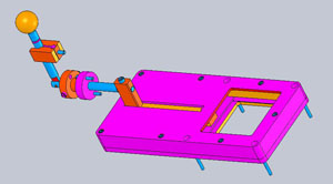 Shutter Model Shutter Model
|